
Active Body Ventilation System

a ventilation system and active body technology, applied in the field of body ventilation, can solve the problems of air compression within the body, difficult door closure, and give any occupant the sensation of an ear pop at the door closure, so as to reduce the opening size of the portal and increase or decrease the size of the opening

Inactive Publication Date: 2008-08-07
GM GLOBAL TECH OPERATIONS LLC
View PDF4 Cites 7 Cited by
  • Summary
  • Abstract
  • Description
  • Claims
  • Application Information

AI Technical Summary

Benefits of technology

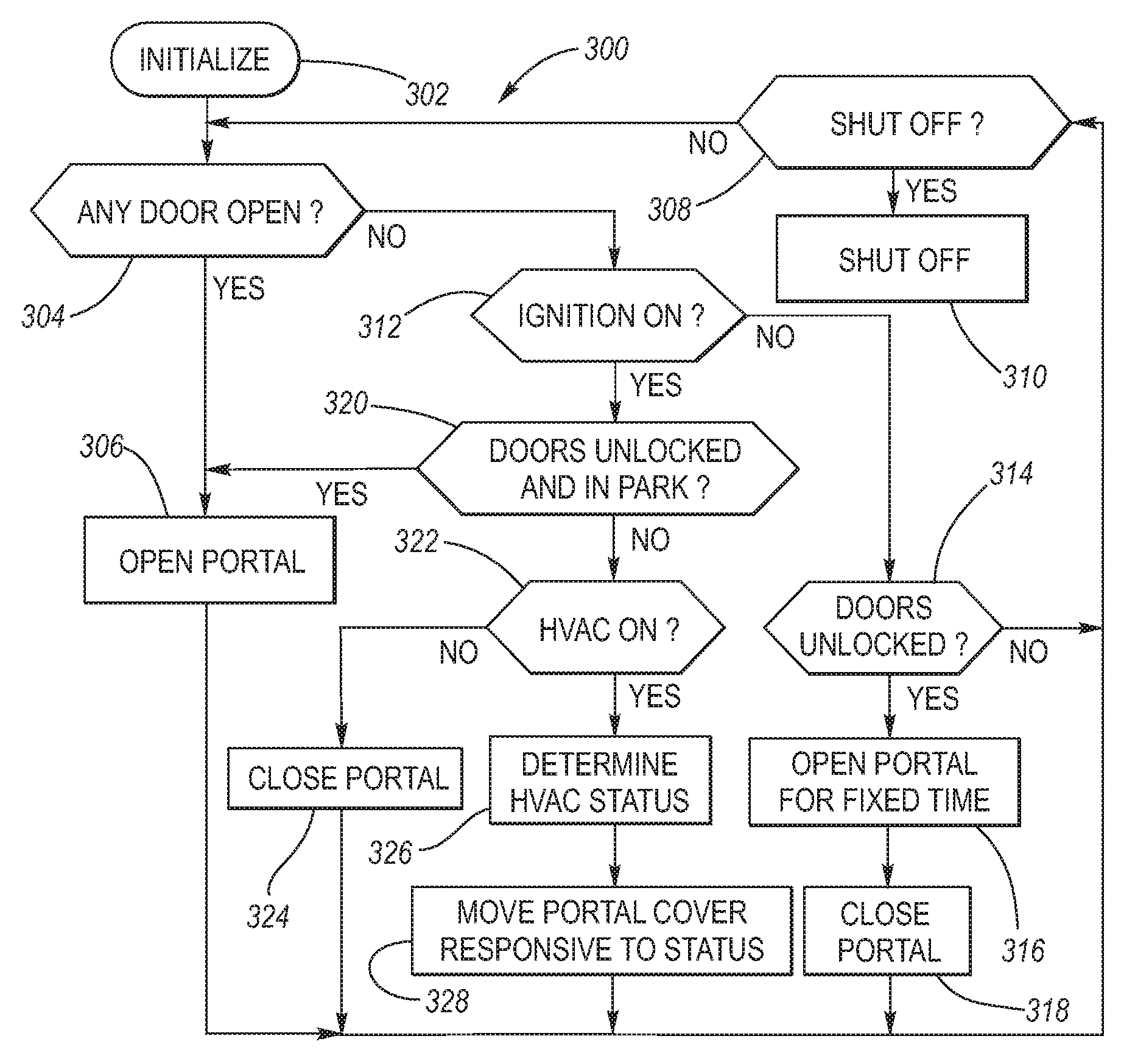
[0011]Accordingly, it is an object of the present invention to provide an active body ventilation system which is dynamically responsive to vehicle status parameters, including for example the door open / closed status and the HVAC system status.

Problems solved by technology

This in rush of air creates a pressure increase (air compression) within the body which needs release to the atmosphere, otherwise the increase in pressure will make full closure of the door difficult and also give any occupant the sensation of an ear pop at closure.
Indeed, when one considers a door in the form of a decklid, the closure of the decklid can also cause air compression within the body, as for example by air flowing through the back seat.
The passengers need ventilation, and when the HVAC system is active, the fan and / or the vehicle movement draws air into the body, thereby causing an increase in air pressure within the passenger compartment.
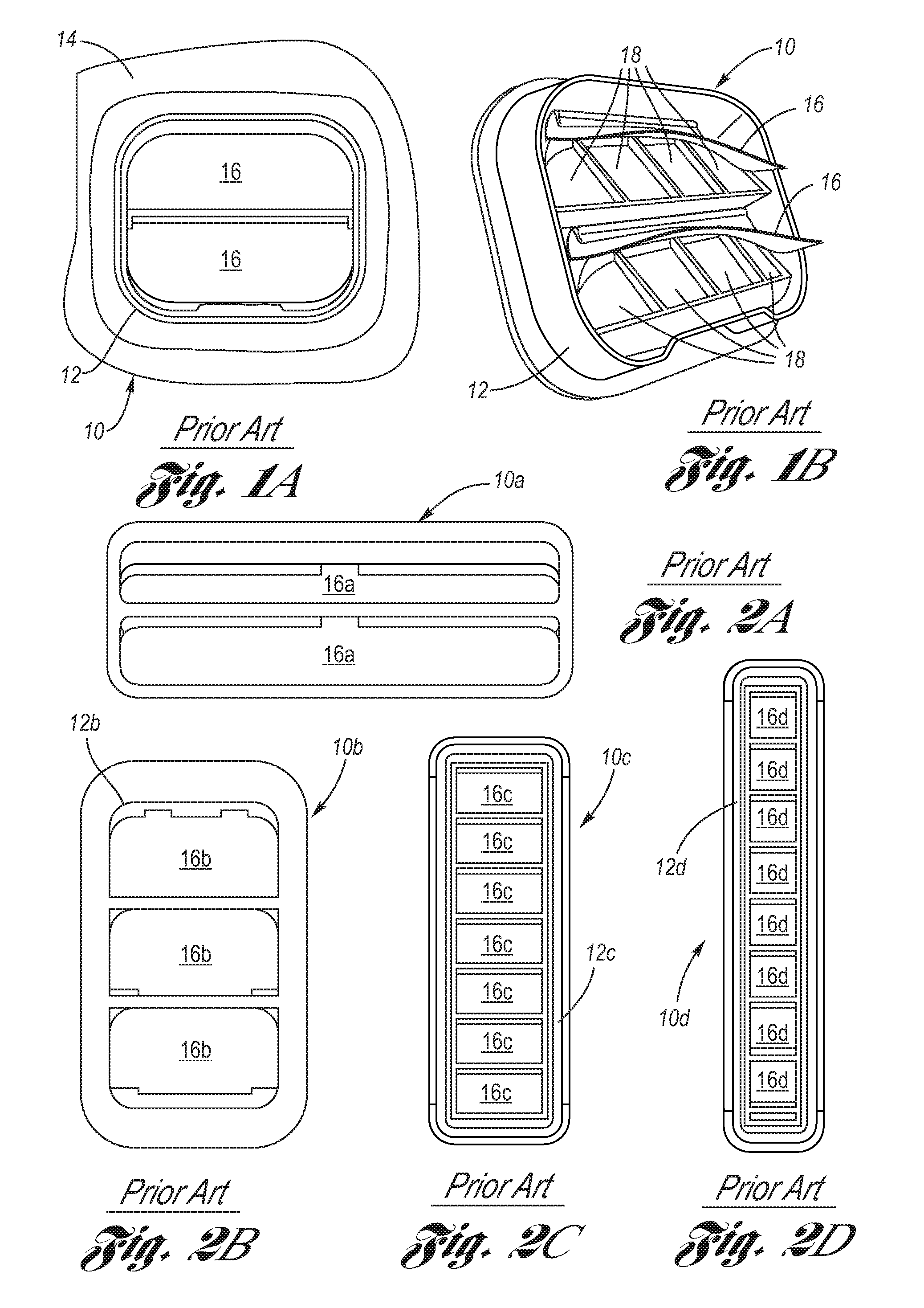
While flap valves are simple and generally inexpensive components, they suffer from certain drawbacks.
One significant draw back is that a flap valve is inherently unable to provide a high level of road noise isolation with respect to the passenger compartment.
For another, the passive nature of flap valves does not allow for dynamic response to the operational status of the HVAC system.
Still further, since the resiliency and response rate of the flaps of the flap valves is preset, there is always going to be some air compression inside the passenger compartment when a door is shut which will require additional door push energy to overcome; and if a door is slammed, passenger ear discomfort may be sensed.

Method used


Image

  • Active Body Ventilation System
  • Active Body Ventilation System
  • Active Body Ventilation System

Examples


first embodiment

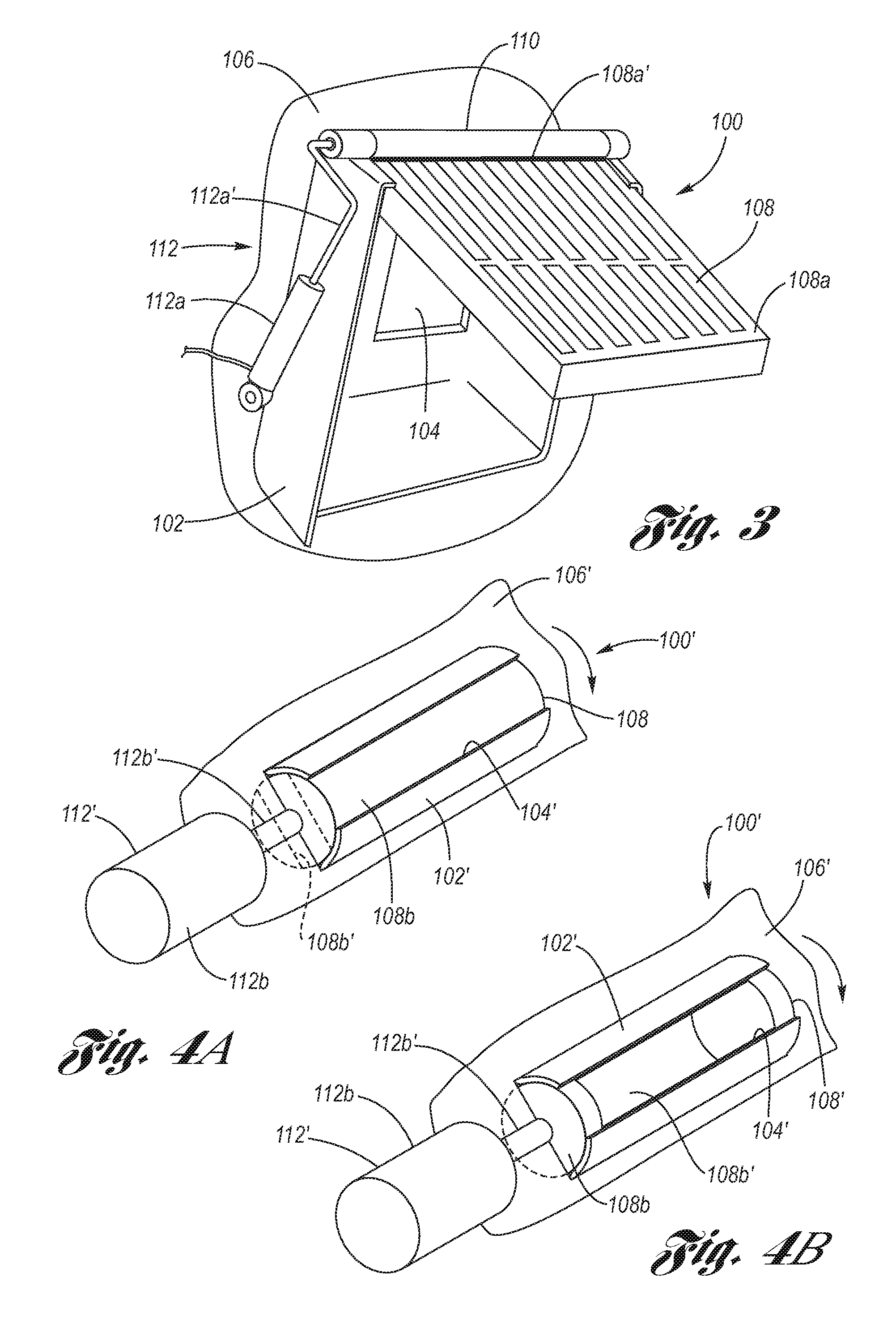
[0026]Referring firstly to FIG. 3, an example of an active ventilation unit 100 according to the active body ventilation system 200 (see FIG. 7) is depicted. The active ventilation unit 100 includes a portal housing 102 which defines a portal 104 having a predetermined portal opening size. The portal housing 102 is attached to a body wall 106 of the vehicle body such that the portal provides an opening therethrough which allows for air passage between the passenger compartment and the atmosphere exterior thereto. The active ventilation unit 100 further includes a portal cover 108 which is movably attached to the portal housing 102. The portal cover may have sound deadening material applied thereto as an added barrier to road noise passing therethrough. In the example of FIG. 3, the portal cover 108 is composed of a panel 108a, wherein a top edge 108a′ thereof is pivotally connected to hinge mechanism 110. The active ventilation unit 100 still further includes a portal cover actuator...

second embodiment

[0028]Referring to FIGS. 4A and 4B, an example of an active ventilation unit 100′ according to the active body ventilation system 200 is depicted. The active ventilation unit 100′ includes a portal housing 102′ which defines a portal 104′ having a predetermined portal opening size. The portal housing 102′ is attached to a body wall 106′ such that the portal passes therethrough and provides an air passage with respect to the passenger compartment and the atmosphere exterior thereto. The active ventilation unit 100′ further includes a portal cover 108′ which is movably attached to the portal housing 102′. In the example of FIGS. 4A and 4B, the portal cover 108′ is composed of an apertured cylindrical drum 108b rotatably mounted to the portal housing 102′. The aperture 108b′ of the drum 108b selectively aligns with the portal depending upon the rotational position thereof. The active ventilation unit 100′ still further includes a portal cover actuator 112′ for selectively moving the po...

third embodiment

[0029]Referring to FIGS. 5A and 5B, an example of a ventilation unit 100″ according to the active body ventilation system 200 is depicted. The active ventilation unit 100″ includes a portal housing 102″ which defines a portal 104″ having a predetermined portal opening size. The portal housing 102″ is attached to a body wall 106″ such that the portal passes therethrough and provides an air passage with respect to the passenger compartment and the atmosphere exterior thereto. The active ventilation unit 100″ further includes a portal cover 108″ which is movably attached to the portal housing 102″. In the example of FIGS. 5A and 5B, the portal cover 108″ is composed of a panel 108c slidably mounted, via a channel 120, to the portal housing 102″. The active ventilation unit 100″ still further includes a portal cover actuator 112″ for selectively moving the portal cover 108″ (i.e., sliding the panel 108c) between a fully open position as shown at FIG. 5A (whereat the panel has been slid ...


PUM


Abstract

An active body ventilation system which is dynamically responsive to vehicle status parameters, including for example the door open / closed status and the HVAC system status. An active ventilation unit is attached with a body wall which includes a portal housing defining a portal, a portal cover and a portal cover actuator for selectively adjusting the portal cover to thereby increase or decrease the unobstructed size of the opening of the portal. The active ventilation unit is interfaced electronically to various sensors of the motor vehicle, in which programming of an electronic control module determines optimum positioning of the portal covering via selective actuation of the portal cover actuator.

Description

TECHNICAL FIELD[0001]The present invention relates to body ventilation of the passenger compartment of motor vehicles, and more particularly to a body ventilation system which is actively responsive to changes in sensed motor vehicle parameters.BACKGROUND OF THE INVENTION[0002]The passenger compartment of motor vehicles provides a space which provides protection to the occupants from environmental elements. To this end, the body of the vehicle defining the passenger compartment is preferably tight fitted at the door (by the term “door” is meant an expansive definition which includes doors, hatches, liftglass, decklids (trunklid), liftgates, etc.) and window seams, and provides an enclosure which keeps out dust, wind and water, and minimizes the passenger perception of road noise. In this respect, the more air-tight the body, the better. However, the air-tight quality of the body defining a passenger compartment must not be too air-tight for purposes of ease of closing a door and for...

Claims


Application Information

Patent Timeline
Patent Type & Authority Applications(United States)
IPC IPC(8): B60Q9/00
CPCB60H1/249B60H1/248
Inventor SHOEMAKER, JAMES H.MIEDINGER, WARREN J.NOVAJOVSKY, ANDREW J.MELONSON, DOUGLAS V.COCHRAN, HEATHER A.
Owner GM GLOBAL TECH OPERATIONS LLC
Learn More