
Mounting Systems for Transverse Front Wheel Drive Powertrains with Decoupled Pitch Damping

a technology of decoupling pitch damping and mounting system, which is applied in the direction of shock absorber, jet propulsion mounting, transportation and packaging, etc., can solve the problems of unable to operate the compliant membrane, and achieve the effect of minimal to no hydraulic damping, high hydraulic damping and stiffness

Inactive Publication Date: 2012-04-19
GM GLOBAL TECH OPERATIONS LLC
View PDF10 Cites 16 Cited by
  • Summary
  • Abstract
  • Description
  • Claims
  • Application Information

AI Technical Summary

Benefits of technology

[0010]The present invention packages a hydraulic device into a torque reacting mount bushing of a torque reacting mount component of a powertrain mounting system, for example an NTA or pendular mounting system, so as to provide high hydraulic damping and stiffness at high vibration amplitude, and minimal to no hydraulic damping and stiffness at low vibration amplitude, thereby enabling the mounting system to have passively decoupled powertrain pitch damping as between high and low amplitudes of vibration.
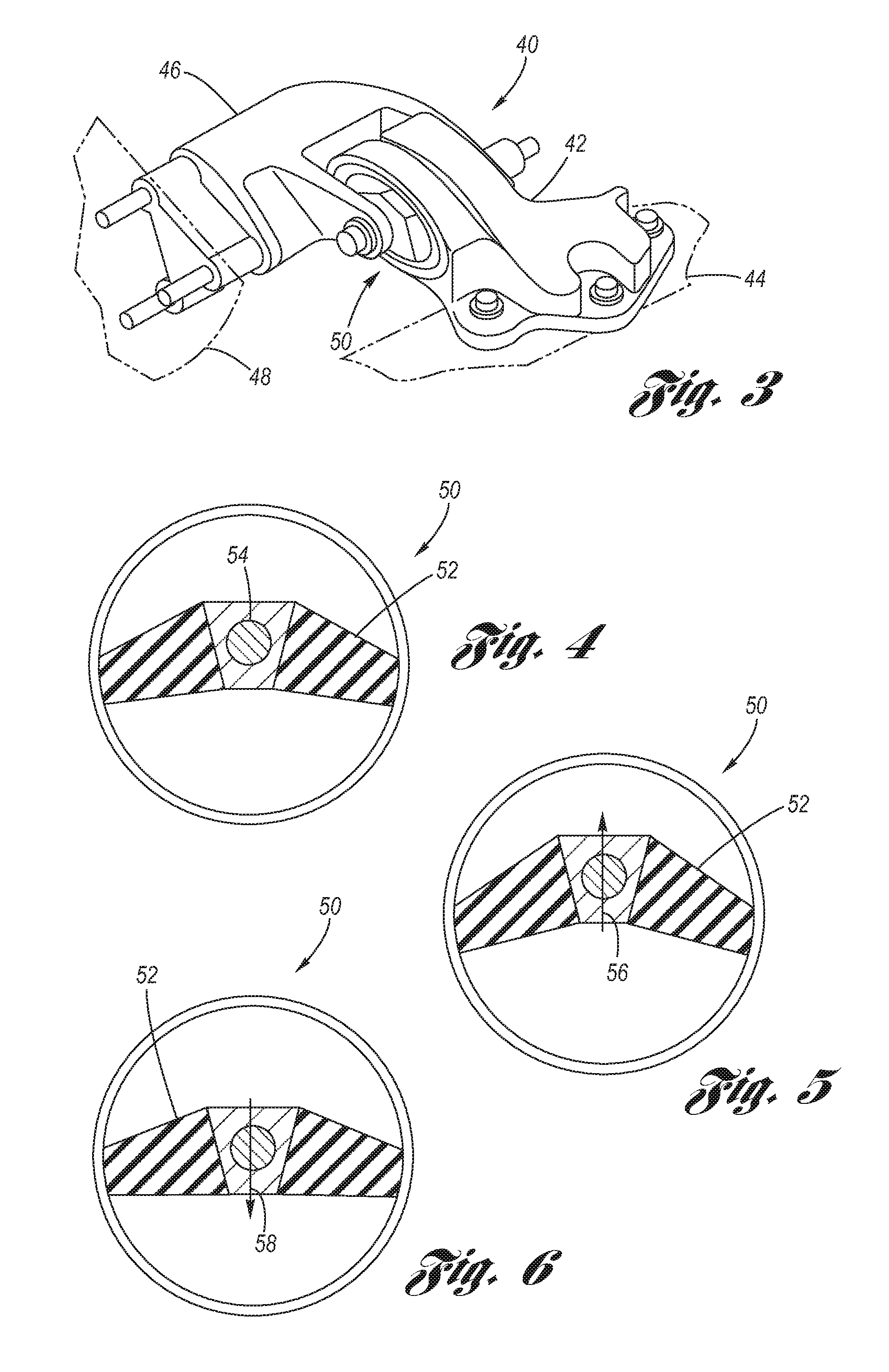
[0013]In operation, vibrations of low amplitude are transmitted by the main elastic element to the main liquid reservoir and because the compliant membrane is free to move, the vibrations passing through the main liquid reservoir transmit through the decoupler system into the decoupler fluid passage, whereby low pitch stiffness and low to no hydraulic damping will be provided. For vibrations of high amplitude, the vibrations are transmitted by the main elastic element to the main liquid reservoir such that liquid is displaced (in or out) of the main liquid reservoir and exchanged with the secondary liquid reservoir via the bounce inertia track and resilient compliance of the bellows. At the same time, the amplitude of the vibration causes the compliant membrane of the decoupler system to be hydraulically pressed into occluding relation with a perforated sidewall of the decoupler system, thereby disabling operation of the compliant membrane. Thus, for high amplitude vibrations, high hydraulic damping and high pitch stiffness are provided. Accordingly, provided are high hydraulic damping and stiffness at high vibration amplitude, and minimal to no hydraulic damping and stiffness at low vibration amplitude, enabling the mounting system to have passively decoupled pitch damping at high and low amplitudes of vibration.
[0014]Accordingly, it is an object of the present invention to utilize a hydraulic device as the torque reacting mount bushing of a torque reacting mount component of a powertrain mounting system, for example an NTA or pendular mounting system, so as to provide high hydraulic damping and stiffness at high vibration amplitude, and minimal to no hydraulic damping and stiffness at low vibration amplitude, thus enabling the mounting system to have passively decoupled pitch damping as between high and low amplitudes of vibration.

Problems solved by technology

At the same time, the amplitude of the vibration causes the compliant membrane of the decoupler system to be hydraulically pressed into occluding relation with a perforated sidewall of the decoupler system, thereby disabling operation of the compliant membrane.

Method used


Image

  • Mounting Systems for Transverse Front Wheel Drive Powertrains with Decoupled Pitch Damping
  • Mounting Systems for Transverse Front Wheel Drive Powertrains with Decoupled Pitch Damping
  • Mounting Systems for Transverse Front Wheel Drive Powertrains with Decoupled Pitch Damping

Examples


Embodiment Construction

[0027]Referring now to the Drawings, aspects of a hydraulic device torque reacting mount bushing for a torque reacting mount component of a powertrain mounting system according to the present invention are depicted in FIGS. 7 through 14.

[0028]FIG. 7 schematically depicts the structural and functional principles of operation of a hydraulic device torque reacting mount bushing 1000 according to the present invention.

[0029]A rigid outer shell 1004 connects to a first torque reacting mount component member 1002′. A main elastic element 1006 has a generally centrally disposed insert 1014 which is connected to a second torque reacting mount component member 1002″. A main liquid reservoir 1022 is disposed sealingly on a first side 1006′ of the main elastic element 1006, while the other, second, side 1006″ of the main elastic element is exposed to the atmosphere 1024. A bounce inertia track 1026 hydraulically connects to the main liquid reservoir 1022 and extends to a secondary liquid reser...


PUM


Abstract

A powertrain mounting system with a decoupled hydraulic bushing device as a torque reacting element. An elastic element of the bushing mount vibrates in response to powertrain pitch torque. At high vibration amplitude of the elastic element, high hydraulic damping is provided via a main liquid reservoir, bounce inertia track and bellowed secondary liquid reservoir, with a decoupler fluid passage being passively disabled. At low vibration amplitude of the elastic element, minimal hydraulic damping is provided via a decoupler system.

Description

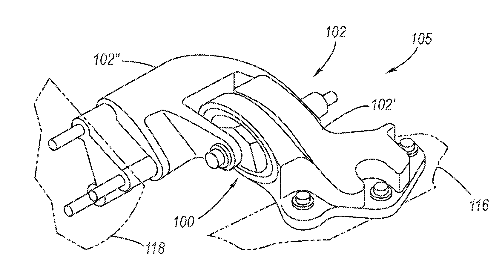
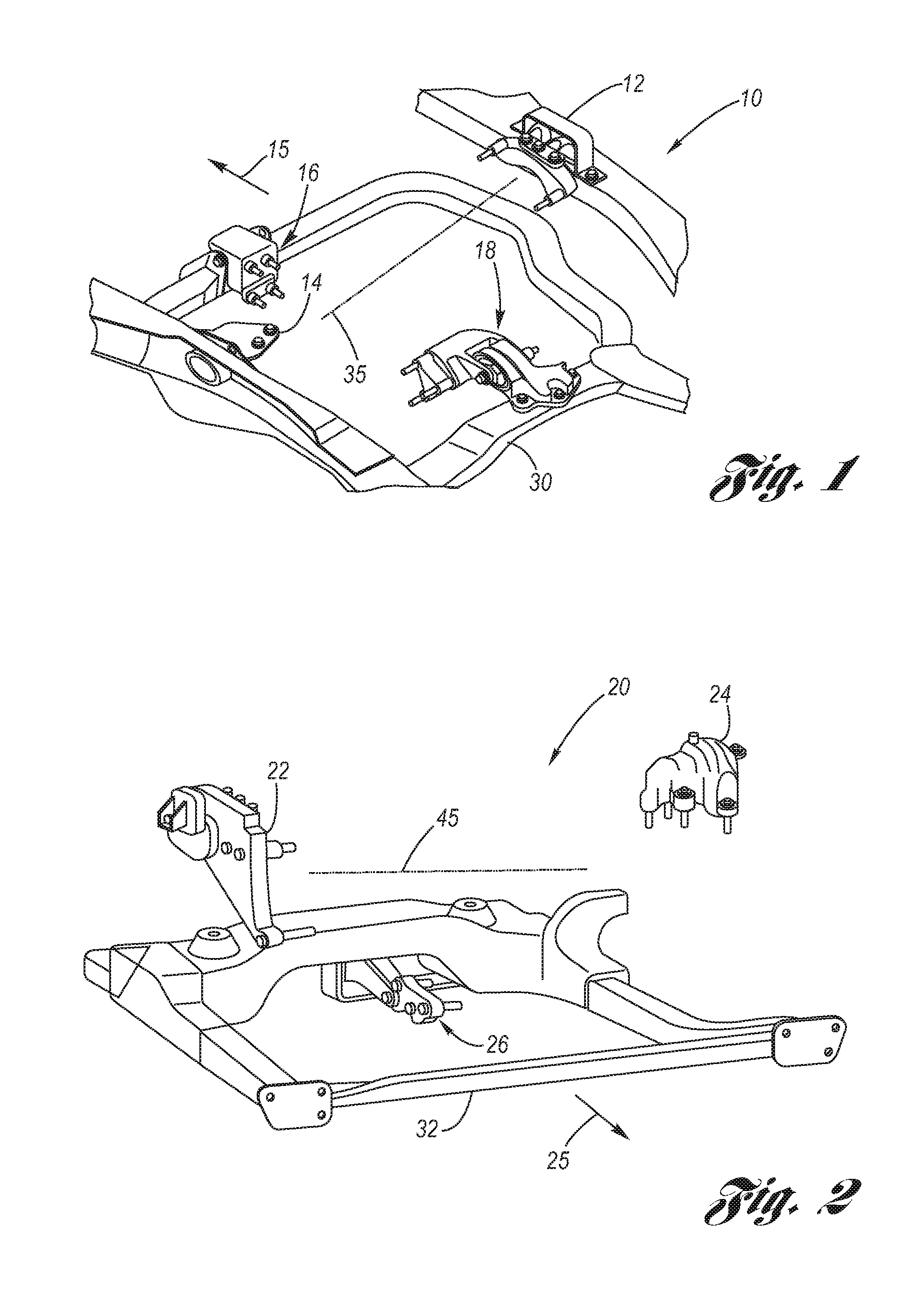
TECHNICAL FIELD[0001]The present invention relates to mounting systems used for mounting a powertrain in motor vehicle applications, particularly to neutral torque roll axis mounting systems and pendular mounting systems, and more particularly to a fully decoupled pitch damping hydraulic bushing at the torque reacting mount components thereofBACKGROUND OF THE INVENTION[0002]Powertrain mounting systems used in motor vehicle applications include the “four-point neutral torque roll axis” (hereafter simply “NTA”) mounting system, exemplified at FIG. 1, and the “pendular” mounting system, exemplified at FIG. 2. In the NTA mounting system 10 of FIG. 1, there is included (dispositions being relative to forward travel direction 15 of the motor vehicle) a right-hand load bearing mount 12, a left-hand load bearing mount 14, a front torque reacting bushing mount 16, and a rear torque reacting bushing mount 18. In the pendular mounting system 20 of FIG. 2, there is included (dispositions being ...

Claims


Application Information

Patent Timeline
Patent Type & Authority Applications(United States)
IPC IPC(8): B60K5/12B60K17/00B62D21/00
CPCB60K5/04F16F13/14B60K5/1216
Inventor GANNON, DANIEL G.JOMAA, SAM M.LEE, PINGKINCHEN, DENNIS J.
Owner GM GLOBAL TECH OPERATIONS LLC
Learn More