
Systems and devices for electrical filters

a technology of electrical filters and systems, applied in the field of superconducting high frequency dissipation filters, can solve the problems of limited physical properties that can be provided by a single material, such as epoxy, and can only provide a limited dielectric loss range. single-ended signaling can be highly susceptible to nois

Inactive Publication Date: 2012-04-12
D WAVE SYSTEMS INC
View PDF7 Cites 4 Cited by
  • Summary
  • Abstract
  • Description
  • Claims
  • Application Information

AI Technical Summary

Problems solved by technology

In general, the range of physical properties that can be provided by a single material, such as epoxy, is limited.
Epoxy can only provide a limited range of dielectric loss tangent, thus, there remains a need in the art for alternative metal powder filter designs for applications where epoxy is insufficient as the binder material or is otherwise undesired for use as the binder material.
However, single-ended signaling can be highly susceptible to noise that is picked up (during transmission) by the signal wire and / or the ground path, as well as noise that results from fluctuations in the ground voltage level throughout the system.
Thus, any fluctuations in the signal and / or reference voltage that occur between sending and receiving the signal can result in a discrepancy between the signal that enters the signal wire and the signal that is received by the receiving circuit.
Thus, if the first wire and the second wire are maintained in close proximity throughout the signal transmission, any noise coupled to the data signal is likely also to couple to the reference signal and therefore any such noise may be cancelled out in the receiving circuit.
The main disadvantage of differential signaling is that it uses approximately twice as many wires as single-ended signaling.
However, in some applications this disadvantage is more than compensated by the improved signal-to-noise ratio of differential signaling.

Method used


Image

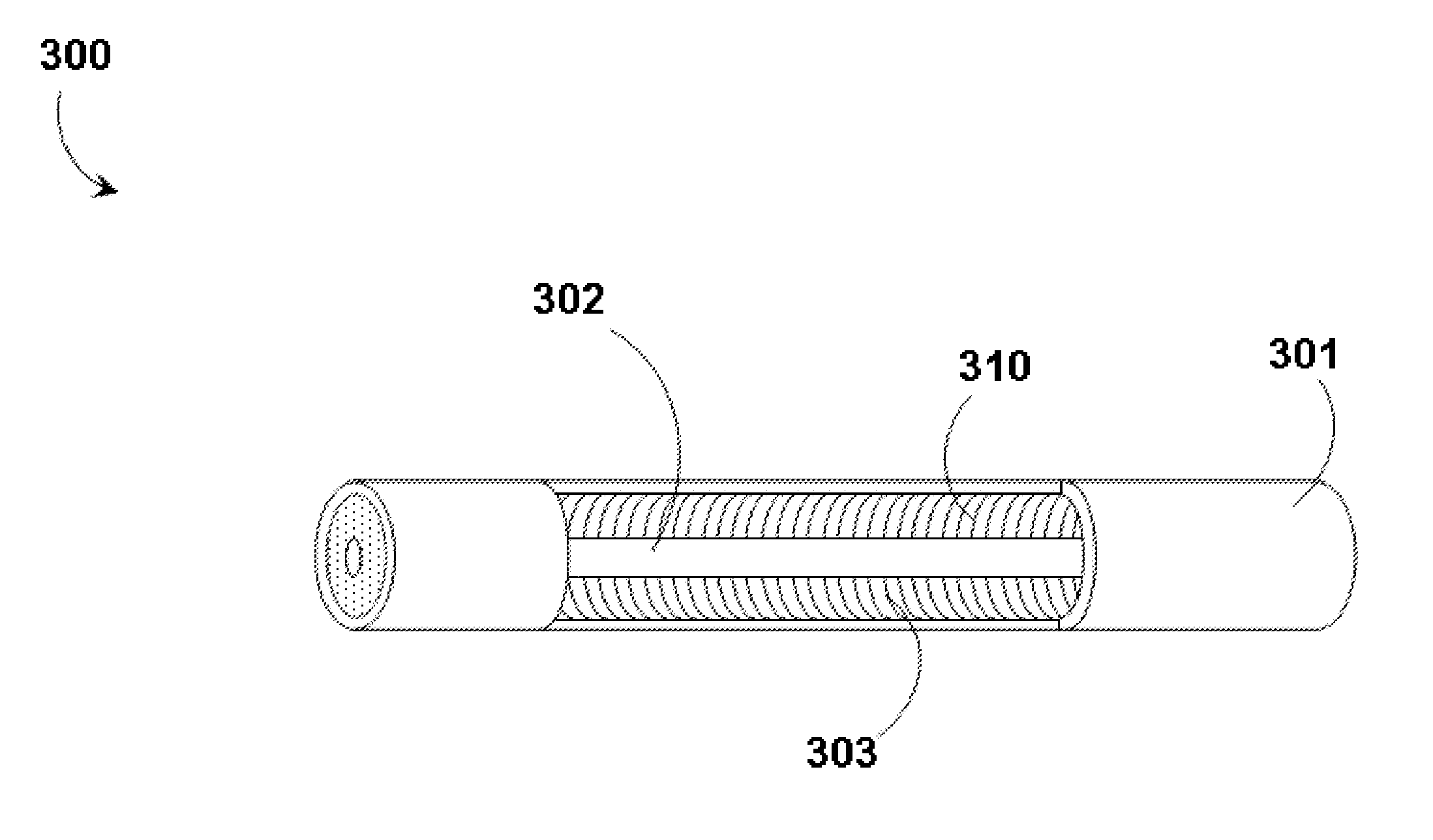
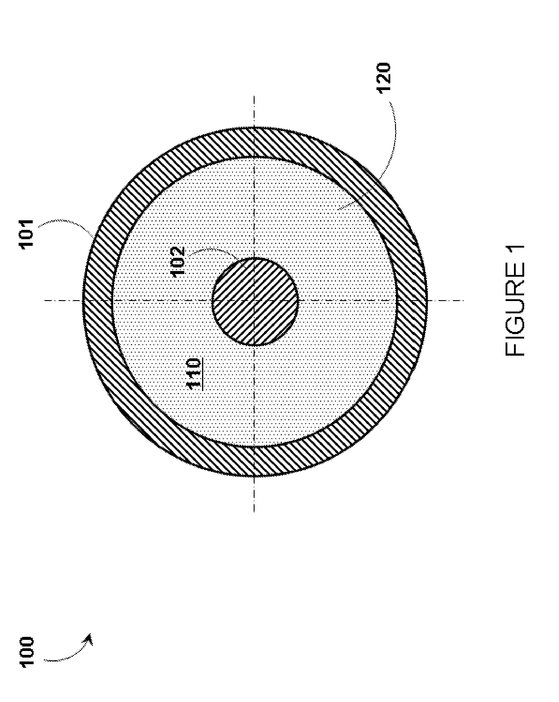
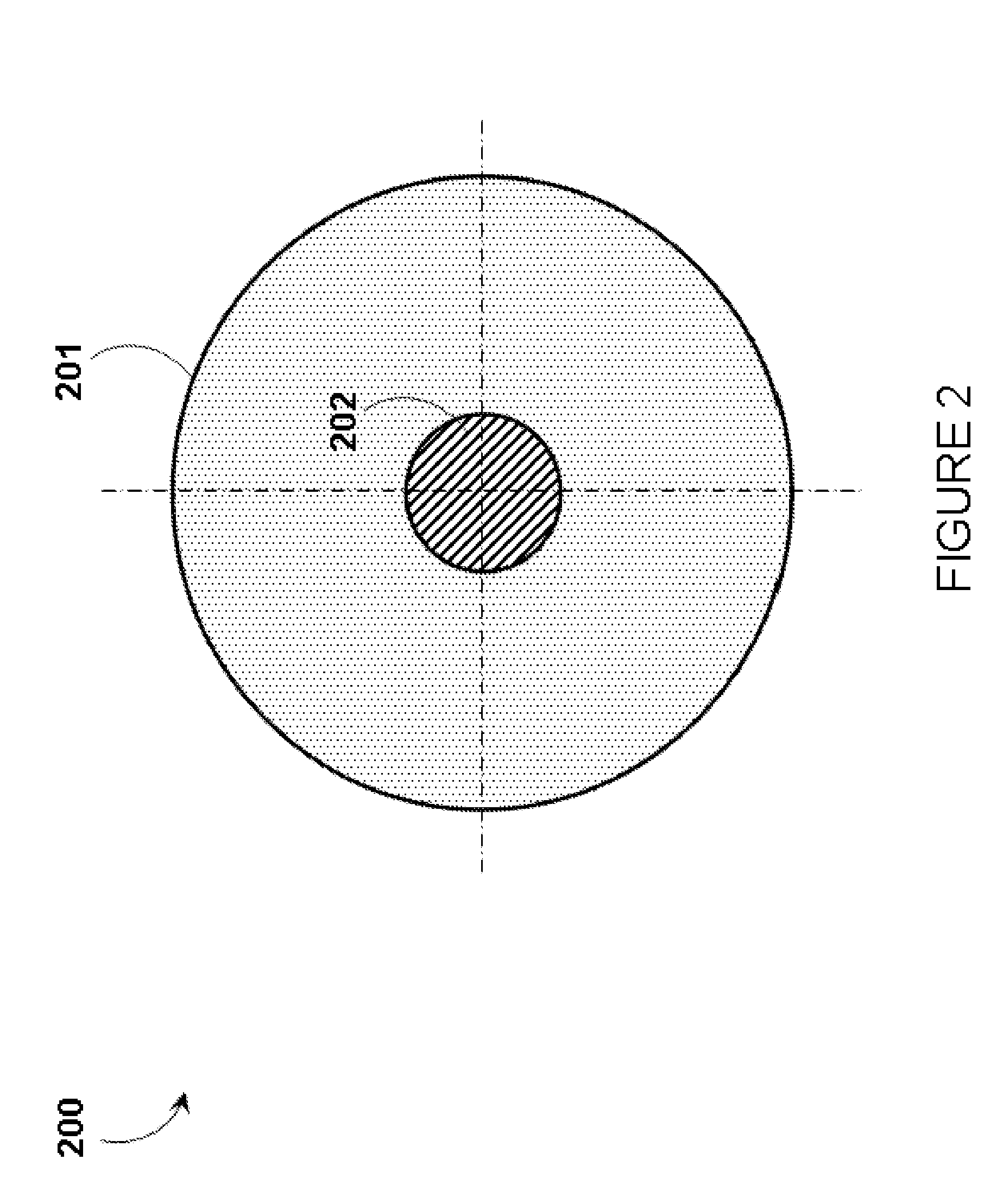
  • Systems and devices for electrical filters
  • Systems and devices for electrical filters
  • Systems and devices for electrical filters

Examples


Embodiment Construction

[0020]In the following description, some specific details are included to provide a thorough understanding of various disclosed embodiments. One skilled in the relevant art, however, will recognize that embodiments may be practiced without one or more of these specific details, or with other methods, components, materials, etc. In other instances, well-known structures associated with electrical filters have not been shown or described in detail to avoid unnecessarily obscuring descriptions of the embodiments of the present systems and devices.

[0021]Unless the context requires otherwise, throughout the specification and claims which follow, the word “comprise” and variations thereof, such as, “comprises” and “comprising” are to be construed in an open, inclusive sense, that is as “including, but not limited to.”

[0022]Reference throughout this specification to “one embodiment,” or “an embodiment,” or “another embodiment” means that a particular referent feature, structure, or charact...


PUM


Abstract

Adaptations and improvements to tubular metal powder filters include employing a polyester binder or a binder formed of vacuum grease, employing metal powders of multiple different chemical compositions and / or spanning multiple different ranges of grain-size, replacing the outer conductive housing and metal powder components with a single structure formed of sintered metal powder, and texturing (such as rifling, threading, sanding, or scratching) an inner surface of the outer conductive housing. The various adaptations and improvements are designed to accommodate single-ended and differential signaling, as well as superconducting and non-superconducting applications.

Description

CROSS REFERENCE TO RELATED APPLICATION[0001]This application claims benefit under 35 U.S.C. 119(e) of US Provisional Patent Application Ser. No. 61 / 391,465, filed Oct. 8, 2010, and entitled “Systems and Devices For Electrical Filters,” which is incorporated herein by reference in its entirety.BACKGROUNDField[0002]The present systems and devices generally relate to electrical filters and particularly relate to superconducting high frequency dissipation filters employing tubular geometries.Refrigeration[0003]According to the present state of the art, a superconducting material may generally only act as a superconductor if it is cooled below a critical temperature that is characteristic of the specific material in question. For this reason, those of skill in the art will appreciate that an electrical system that implements superconducting components may implicitly include a refrigeration system for cooling the superconducting materials in the system. Systems and methods for such refrig...

Claims


Application Information

Patent Timeline
IPC IPC(8): H01P1/207H01P1/202
CPCH01L23/295H01P1/202H01P11/005H01L2924/0002H01L2924/00
Inventor PIRES, DAVIDUCHAYKIN, SERGEY V.PETROFF, JACOB CRAIGTCACIUC, ALEXANDR M.
Owner D WAVE SYSTEMS INC
Learn More