
Compact Multi-Element Antenna With Phase Shift

a phase shift and multi-element technology, applied in the field of directional antennas, can solve problems such as reducing the performance of antennas, and achieve the effects of increasing the gain of the antenna system, increasing the length of the overall antenna system, and reducing the negative effects of other elements

Active Publication Date: 2012-04-12
AIRGAIN INC
View PDF10 Cites 6 Cited by
  • Summary
  • Abstract
  • Description
  • Claims
  • Application Information

AI Technical Summary

Benefits of technology

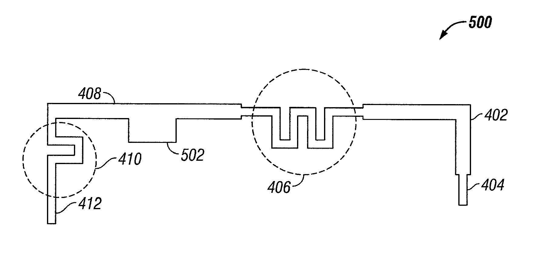
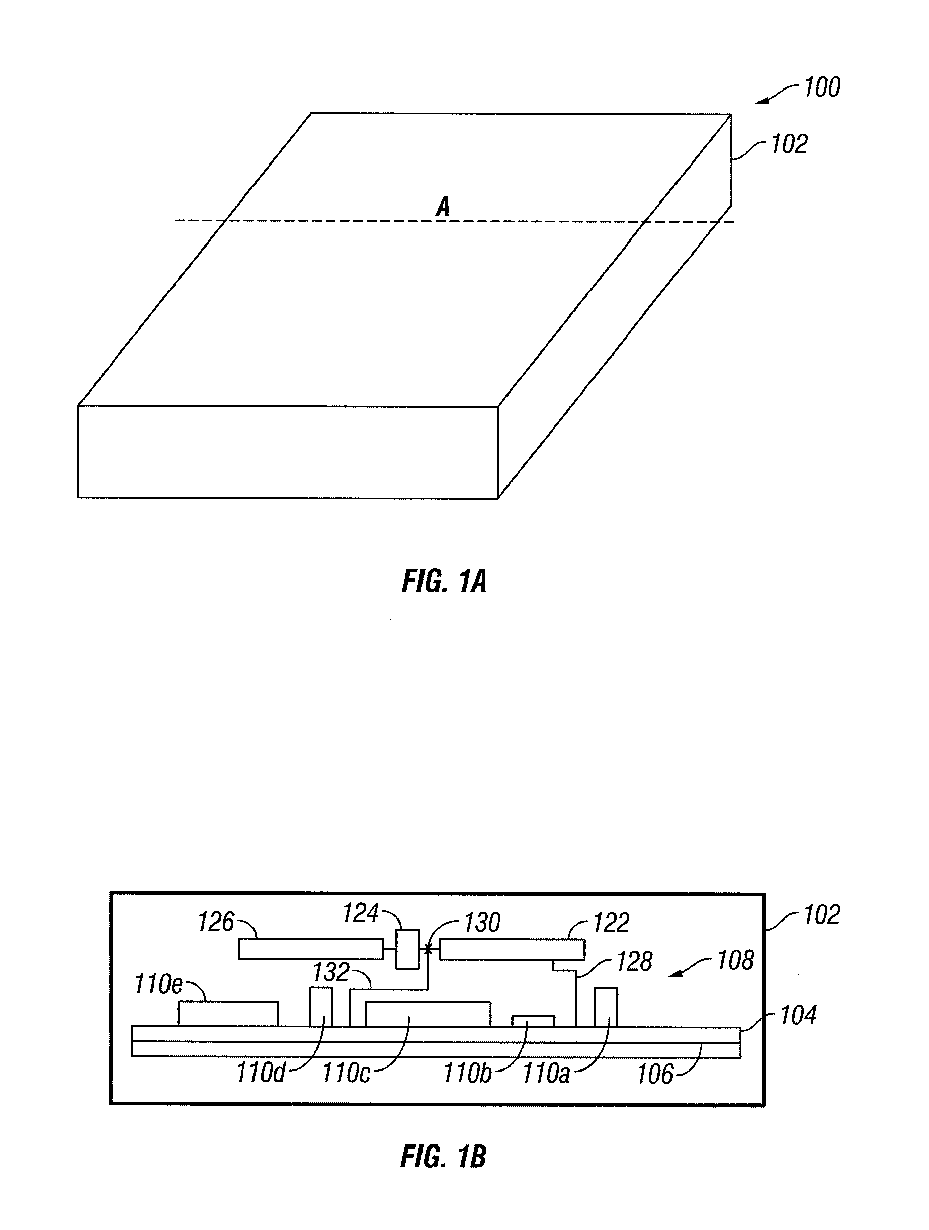
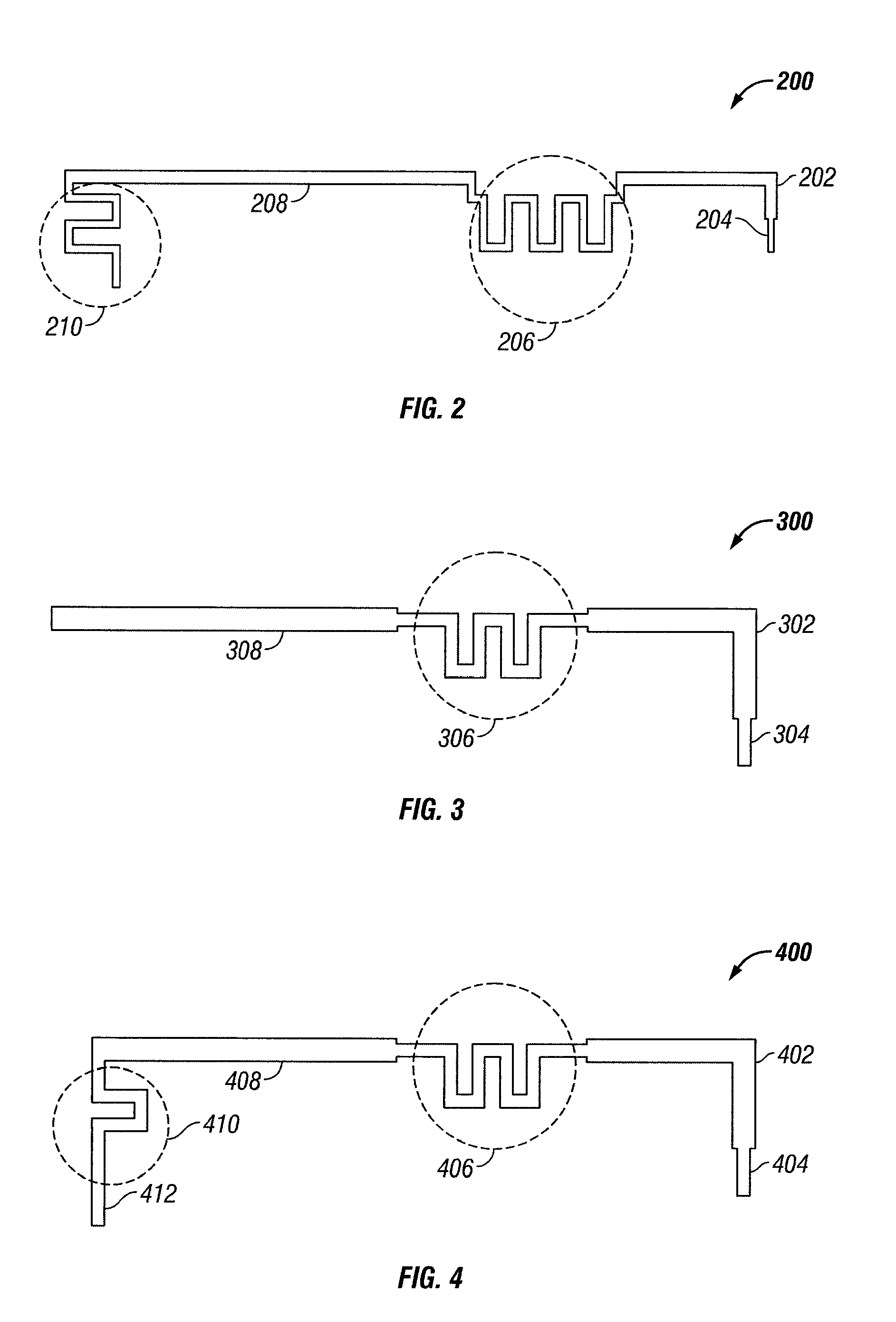
[0008]Methods, apparatuses, and systems are described for antenna systems that can be contained within an enclosure of a device which uses the antenna while providing positive gain. In one aspect the antenna system includes an array of antenna elements which cooperate to form an antenna beam pattern. The antenna elements can be arranged as two or more in-phase antenna elements which cooperate to increase the gain of the antenna system in a desired beam pattern. Using more than one antenna element can increase the length of the overall antenna system which can decrease the negative effects of other elements of the system in the enclosure by limiting those negative effects to a relatively smaller portion of the antenna system. This increases the robustness and tolerance of the antenna system, and allows antennas to be embedded in an enclosure with a printed circuit board assembly (PCBA) or on-board assembly easily. In one aspect, two or more of the antenna systems are used to provide different antenna patterns simultaneously of selectively.

Problems solved by technology

However, placing an antenna within the enclosure and in close proximity to the components of the device, can greatly decrease the performance of the antenna.

Method used


Image

  • Compact Multi-Element Antenna With Phase Shift
  • Compact Multi-Element Antenna With Phase Shift
  • Compact Multi-Element Antenna With Phase Shift

Examples


Embodiment Construction

[0042]Certain embodiments as disclosed herein provide for methods, apparatuses, and systems for communication over a broadband wireless air interface. After reading this description it will become apparent how to implement the invention in various alternative embodiments and alternative applications. However, although various embodiments of the present invention will be described herein, it is understood that these embodiments are presented by way of example only, and not limitation. As such, this detailed description of various alternative embodiments should not be construed to limit the scope or breadth of the present invention as set forth in the appended claims.

[0043]In one embodiment, an antenna can be included within an enclosure of a device which uses the antenna to transmit and receive radio frequency signals. The antenna can be configured to radiate in a desired direction, or pattern, and to thereby provide positive gain in the direction or pattern for the transmitted signa...


PUM


Abstract

A phased array antenna system includes a first radiation element that is made of a material and has a length selected to resonate at a desired frequency. A phase-shift element is coupled to one end of the first radiation element. A second radiation element is coupled to the end of the phase-shift element opposite the first radiation element, so that a radio signal passes through the first radiation element through the phase-shift element and through the second radiation element, the second radiation element is made of a material and has a length selected to resonate such that the first and second radiation elements cooperate to form a desired beam pattern from the antenna system.

Description

CROSS REFERENCE TO RELATED APPLICATION[0001]The present application is a continuation application of U.S. patent application Ser. No. 11 / 866,354, filed on Oct. 2, 2007, which claims the benefit of U.S. Provisional Patent application No. 60 / 827,846, filed Oct. 2, 2006, both of which are hereby incorporated by reference in their entireties.STATEMENT REGARDING FEDERALLY SPONSORED RESEARCH OR DEVELOPMENT[0002]Not ApplicableBACKGROUND OF THE INVENTION[0003]1. Field of the Invention[0004]This invention relates to wireless communication systems, and in particular, to directional antennas used in such systems.[0005]2. Description of the Related Art[0006]In wireless communication systems, antennas are used to transmit and receive radio frequency signals. In general, the antennas can be omni-directional or directional. In many applications there is a benefit to having the antenna located within an enclosure or case which encloses a device that uses the antenna. However, placing an antenna wit...

Claims


Application Information

Patent Timeline
IPC IPC(8): H01Q3/00
CPCH01Q1/38H01Q3/36H01Q5/00H01Q9/285H01Q5/321H01Q21/205H01Q21/28H01Q21/29H01Q21/10
Inventor YANG, XIAO PING
Owner AIRGAIN INC
Learn More