
Jig for round solder ball attachment

a solder ball and attachment technology, applied in the direction of non-electric welding apparatus, manufacturing tools, soldering apparatus, etc., can solve the problems of unnecessary operation, long time-consuming to sense whether the solder ball is attached,

Inactive Publication Date: 2012-04-12
SAMSUNG ELECTRO MECHANICS CO LTD
View PDF11 Cites 6 Cited by
  • Summary
  • Abstract
  • Description
  • Claims
  • Application Information

AI Technical Summary

Benefits of technology

The present invention aims to provide a jig for solder ball attachment that can electrically sense whether solder balls are attached and defective, thus eliminating the need for visual inspection and reducing operation inconvenience. The jig includes a body made of insulating material with holes for attachment and a conductive thin film embedded in the body to make contact with the solder balls. The conductive thin film may be machined to align with the edge of the receiving space.

Problems solved by technology

The bumping process is generally performed by a printing method; however, may be also performed by a method for directly attaching round solder balls to a pad using separate attachment due to limitations such as usage, design, or the like, of the substrate, when manufacturing the bump for the flip chip.
Therefore, the (Patent Document 1) needs to move the jig to the camera and then confirm whether the solder balls are attached, thereby causing the unnecessary operation.
As a result, it takes much time to sense whether the solder balls are attached.

Method used


Image

  • Jig for round solder ball attachment
  • Jig for round solder ball attachment
  • Jig for round solder ball attachment

Examples


Embodiment Construction

[0029]Hereinafter, preferred embodiments of the present invention will be described in more detail with reference to the accompanying drawings.

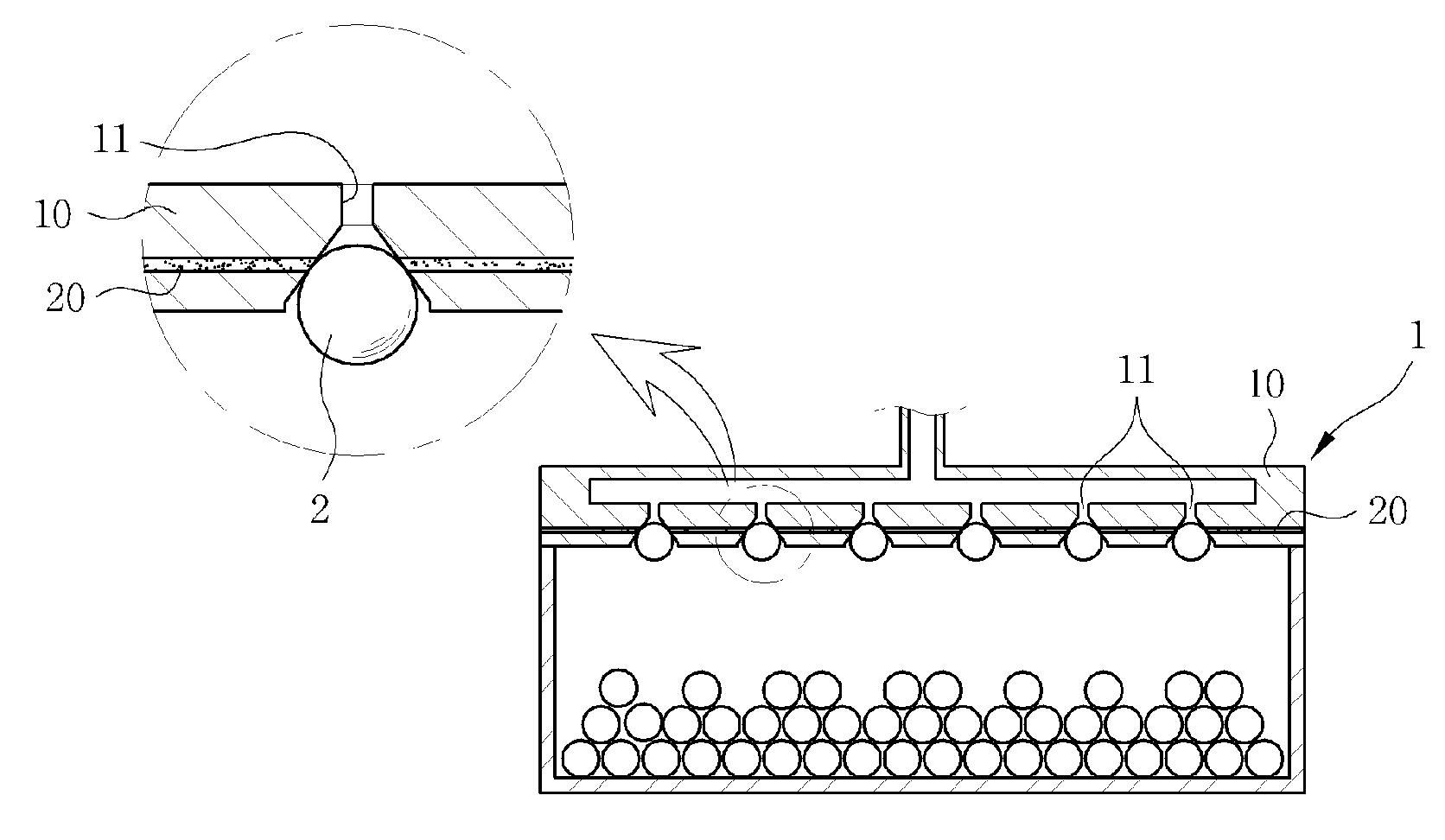
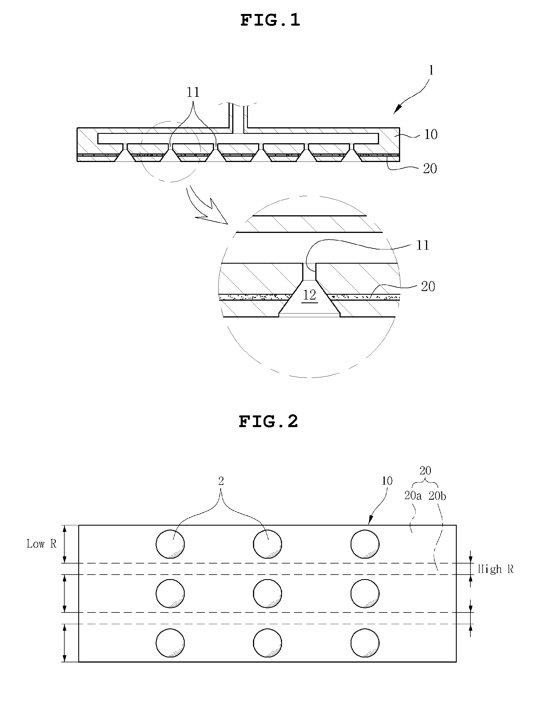
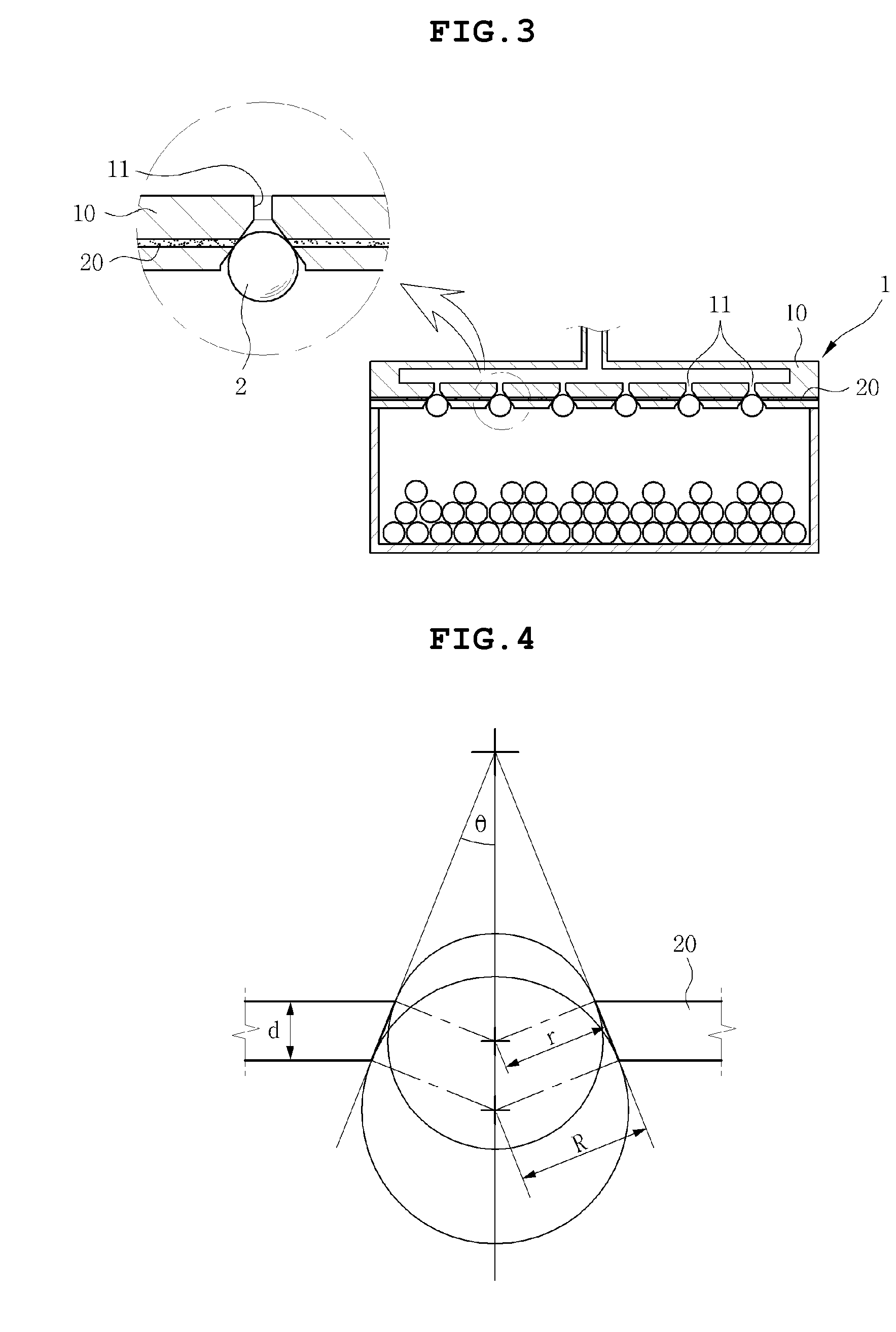
[0030]A jig 1 for solder ball attachment according to a preferred embodiment of the present invention includes a body 10 in which holes 11 for attachment capable of attaching solder balls 2 by a vacuum method is formed, as shown in FIG. 1.

[0031]The body 10 is made of an insulating material such as resin and the holes 11 for attachment formed therein are connected with a vacuum pump (not shown) to attach the solder balls 2 by the vacuum method.

[0032]Meanwhile, the jig 1 according to the preferred embodiment of the present invention includes a conductive thin film 20. The conductive thin film 20 is disposed in the body 10 so as to sense whether the solder balls 2 are attached, in particular, disposed between the holes 11 for attachment.

[0033]Therefore, when measuring a resistance value by applying current to the jig 1 in a state in which the so...


PUM

PropertyMeasurementUnit
thicknessaaaaaaaaaa
thicknessaaaaaaaaaa
conductiveaaaaaaaaaa

Abstract

Disclosed herein is a jig for solder ball attachment capable of sensing whether missing balls occur by electrical sensing using an electrical sensor structure in which a conductive thin film is embedded in the jig and electrically sensing whether abnormal solder balls, for example, large ball / small ball / ball size are attached, without confirming whether abnormal solder balls, for example, large ball / small ball / ball size are attached by vision one by one, thereby shortening operating time and improving workability.

Description

CROSS REFERENCE TO RELATED APPLICATION[0001]This application claims the benefit of Korean Patent Application No. 10-2010-0097772, filed on Oct. 7, 2010, entitled“The Jig For Round Solder Ball Attachment” which is hereby incorporated by reference in its entirety into this application.BACKGROUND OF THE INVENTION[0002]1. Technical Field[0003]The present invention relates to a jig for round solder ball attachment.[0004]2. Description of the Related Art[0005]In manufacturing a flip chip type printed circuit board, one of characteristic processes is a bumping process. The bumping process is generally performed by a printing method; however, may be also performed by a method for directly attaching round solder balls to a pad using separate attachment due to limitations such as usage, design, or the like, of the substrate, when manufacturing the bump for the flip chip.[0006]In this case, the attachment for attaching the solder balls to the pad includes a jig. The bumping process is performe...

Claims


Application Information

Patent Timeline
Patent Type & Authority Applications(United States)
IPC IPC(8): B23K3/06
CPCB23K3/0623
Inventor LEE, SANG YOON
Owner SAMSUNG ELECTRO MECHANICS CO LTD
Learn More