Camera protective system and method

a camera and protection system technology, applied in the field of user protection systems, can solve the problems of posing a safety hazard for individuals who operate, crushing or amputation of the extremity or other injury, and guards are typically unfeasible to prevent such injury

Inactive Publication Date: 2012-04-05
GENERAL ELECTRIC CO
View PDF11 Cites 21 Cited by
  • Summary
  • Abstract
  • Description
  • Claims
  • Application Information

AI Technical Summary

Benefits of technology

[0008]A first aspect of the disclosure provides a protection system for a machine, the protection system comprising: at least one camera directed to a protected area of the machine; a computing device operably coupled to the at least one camera, the computing device including a memory, a processing unit, and a program product stored in the memory which when executed by the processing unit, analyzes at least one image of the protected area captured by the at least one camera and transmitted in real time to the computing device, and a relay coupling operably connecting the computing device with a shut-off control on the machine. In a case in which an object is detected at least partially within the protected area of the machine in the at least one image, the computing device transmits a command to the machine using the relay coupling, the command causing the machine to stop.
[0009]A second aspect of the disclosure provides a machine having a working zone, the machine comprising: a protection system for the working zone, the protection system including: at least one camera directed to a protected area of the machine; a computing device operably coupled to the at least one camera, the computing device including a memory, a processing unit, and a program product stored in the memory which when executed by the processing unit, analyzes at least one image of the protected area captured by the at least one camera and transmitted in real time to the computing device, and a relay coupling operably connecting the computing device with a shut-off control on the machine. In a case in which an object is detected at least partially within the protected area of the machine in the at least one image, the computing device transmits a command to the machine using the relay coupling, the command causing the machine to stop.

Problems solved by technology

Industrial equipment and machines often include moving parts that pose a safety hazard for individuals who operate them.
Operators' hands and other extremities or body parts may be caught between moving parts in the working zone, which can result in crushing or amputation of the extremity or other injury.
Guards are typically unfeasible to prevent such injury for machines which are used with varied thicknesses and sizes of materials.
Injury to a hand or finger may still result, however.
However, this protection system does not provide any measure of protection while operating in the teaching mode.

Method used


Image

  • Camera protective system and method
  • Camera protective system and method
  • Camera protective system and method

Examples


Embodiment Construction

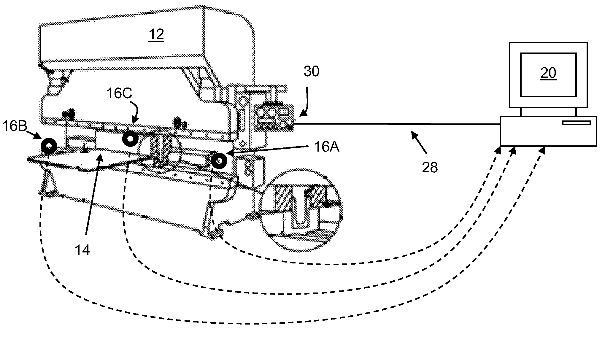
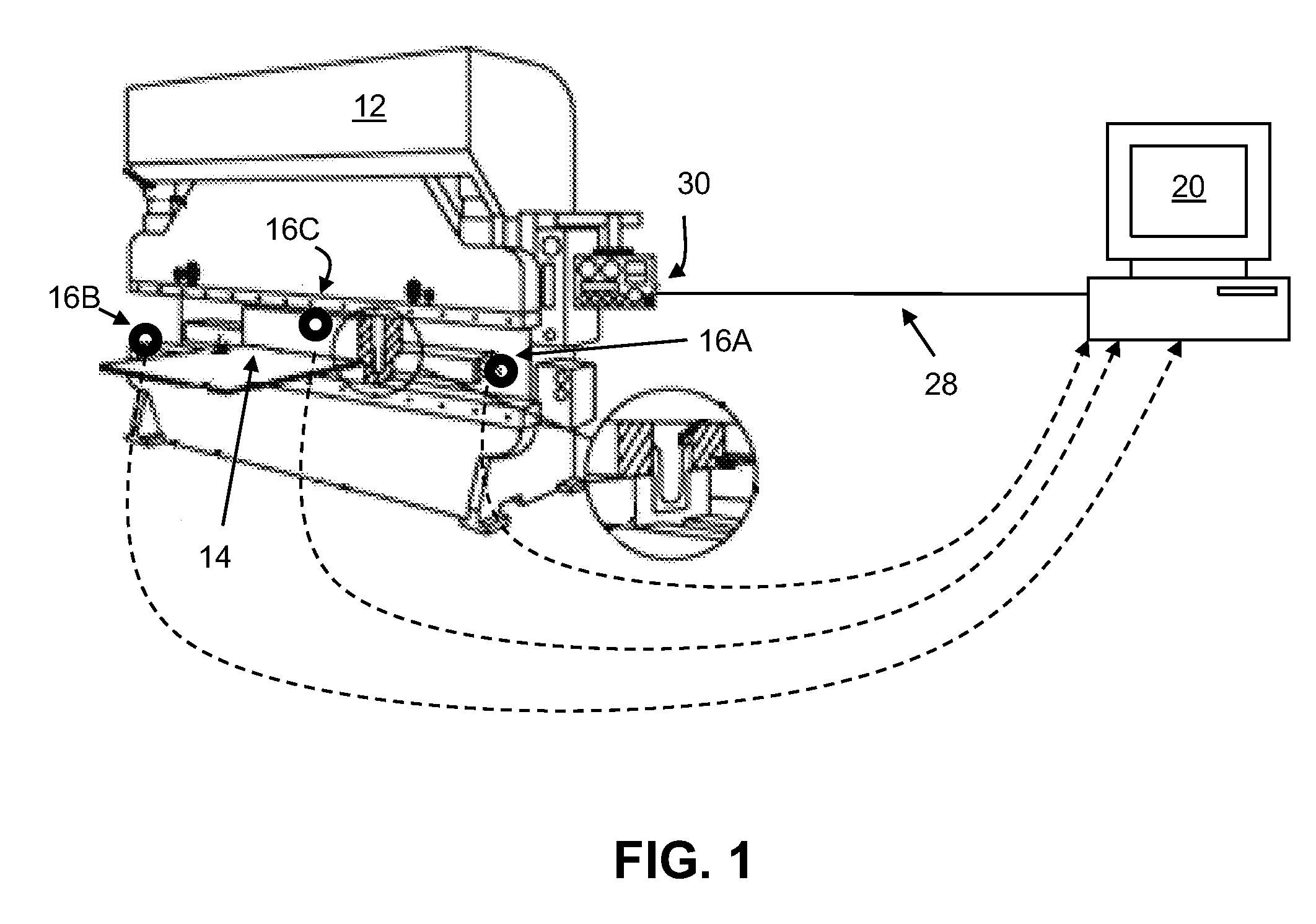
[0015]At least one embodiment of the present invention is described below in reference to its application in connection with the operation of an industrial machine. Although embodiments of the invention are illustrated relative to a machine in the form of a press brake, it is understood that the teachings are equally applicable to other machines and pieces of industrial equipment including, but not limited to, shear presses. Further, at least one embodiment of the present invention is described below in reference to a nominal size and including a set of nominal dimensions. However, it should be apparent to those skilled in the art that the present invention is likewise applicable to any suitable machine and / or piece of equipment. Further, it should be apparent to those skilled in the art that the present invention is likewise applicable to various scales of the nominal size and / or nominal dimensions.

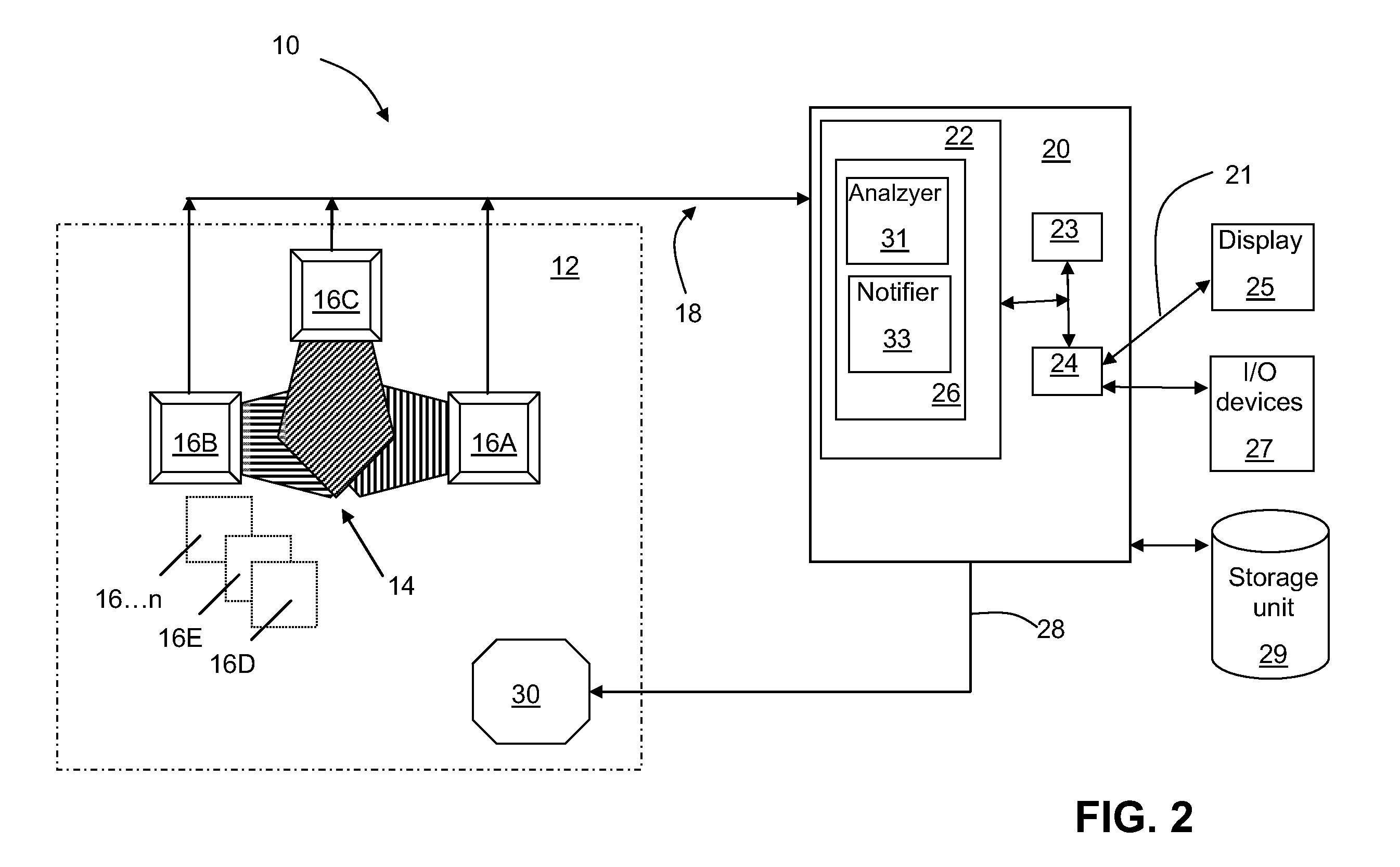
[0016]As indicated above, aspects of the invention provide a user protection system,...


PUM


Abstract

A user protection system, a machine including a user protection system, and a method of protecting a user of a machine are disclosed. In an embodiment, a user protection system is provided including at least one camera directed to a protected area of the machine; a computing device operably coupled to the at least one camera, a program product stored in a memory of the computing device which when executed, analyzes at least one image of the protected area captured by the camera and transmitted in real time to the computing device, and a relay coupling operably connecting the computing device with a shut-off control on the machine, wherein, in a case in which at least a part of a user is detected at least partially within the protected area, the computing device transmits a command causing the machine to stop.

Description

BACKGROUND OF THE INVENTION[0001]The invention relates generally to user protection systems for machines and industrial equipment. More particularly, the invention relates to a camera protection system, and a machine including a camera protection system.[0002]Industrial equipment and machines often include moving parts that pose a safety hazard for individuals who operate them. One such machine is a press brake, a machine typically used to bend sheet metal. A press brake typically includes a pair of vertical frames forming the ends of the press brake machine, a table mounted at the bottom of the frames, and an upper boom or press movably mounted to the top of the frames. A bottom tool is mounted to the table, and a top tool is mounted on the upper beam.[0003]A piece of malleable sheet metal to be pressed or formed into a desired shape is fed into the press brake on the table and aligned over a tool called a die. The press brake lowers the boom onto the sheet metal and applies force,...

Claims


Application Information

Patent Timeline
Patent Type & Authority Applications(United States)
IPC IPC(8): H04N7/18
CPCF16P3/14F16P3/144F16P3/142
Inventor ARCAND, SEBASTIENHEBERT, MARC-ANDRE
Owner GENERAL ELECTRIC CO
Why Eureka
Try Eureka