Combining data from multiple image sensors
a technology of image data and data, applied in the field of combining data from multiple image sensors, can solve the problems of synchronization and alignment challenges, the filtering of image data from multiple sensors, and the complexity of interleaving such image data, so as to avoid stream contamination
- Summary
- Abstract
- Description
- Claims
- Application Information
AI Technical Summary
Benefits of technology
Problems solved by technology
Method used
Image
Examples
embodiment 300
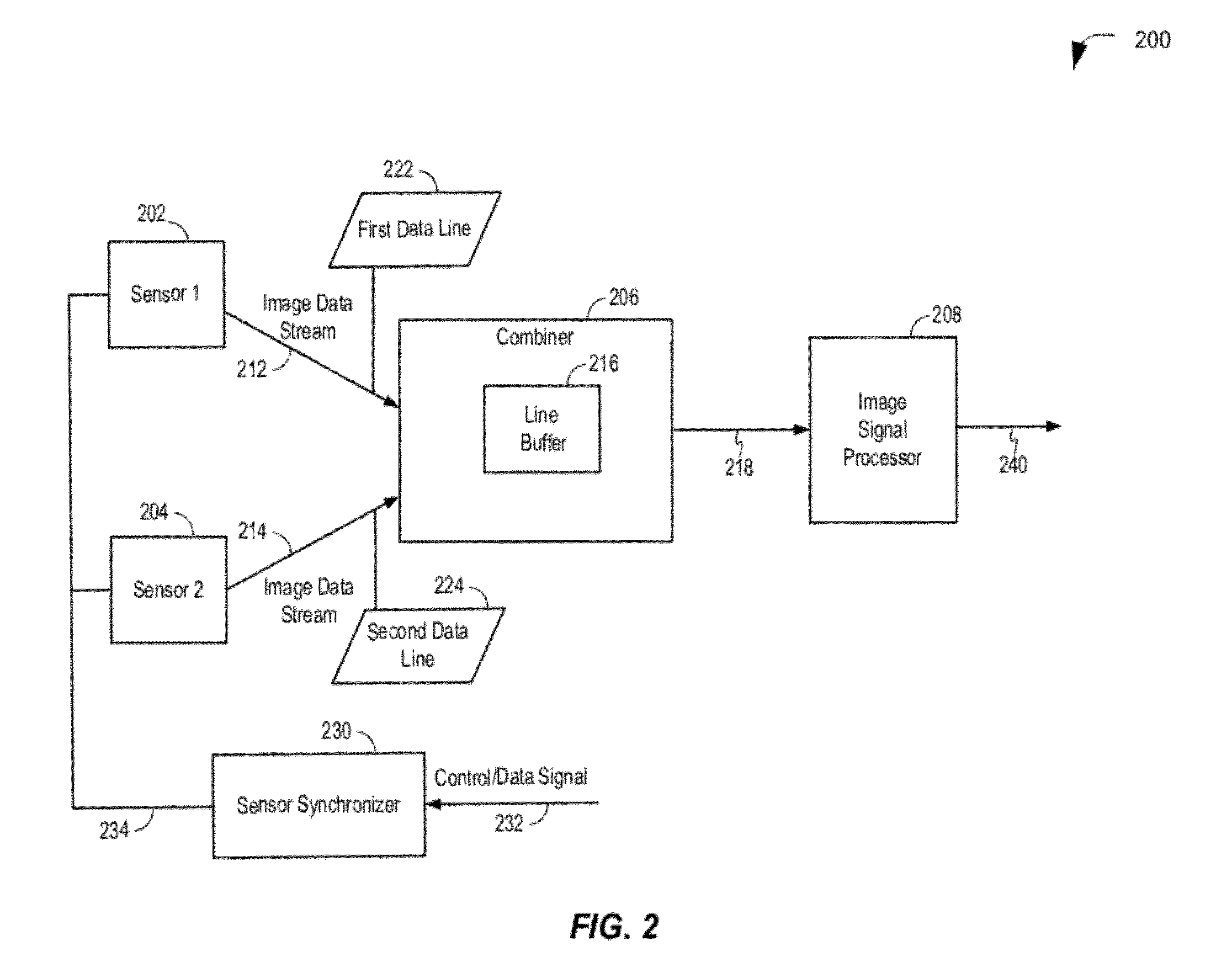
[0062]The image signal processor 208 is configured to process the line data 218 and to generate processed line data 240. In a particular embodiment, the processed line data 240 may be provided as processed frame data. While two sensors have been shown, it should be understood that other embodiments may include more than two sensors. For example, FIG. 3 depicts an embodiment 300 that includes more than two sensors. An Nth sensor 305 is configured to generate an Nth data stream, illustrated as an Nth image data stream 315. The Nth image data stream 315 includes an Nth data line 325. The Nth sensor 305 may be substantially similar to the first and second image sensors 202, 204 and may receive the common control signal 234 from the sensor synchronizer 230, enabling the first, second, and Nth sensors 202, 204, 305 to generate closely aligned data streams 212, 214, 315. For example, the data streams 212, 214, 315 may have substantially the same timing characteristics, such as frequency an...
second embodiment
[0085]Referring to FIG. 7, a diagrammatic representation of a first data stream at an output of a first image sensor and a second data stream at an output of a second image sensor being combined to form a synchronized data line is depicted and generally designated as 700. A first sensor, such as the first image sensor 202 of FIG. 2, generates a first data stream 702 that corresponds to first image data of an image. A second sensor, such as the second image sensor 204 of FIG. 2, generates a second data stream 704 that corresponds to second image data of the image. Data from the first data stream 702 and data from the second data stream 704 are combined to form a data out data stream 706.
[0086]In a particular embodiment, the first data stream 702 includes data associated with a first line of the first image data of the image and the second data stream 704 includes data associated with a corresponding line of the second image data of the image. The first data stream 702 includes line d...
first embodiment
[0091]Referring to FIG. 8, a diagrammatic representation of a phase diagram illustrating a two line phase difference between a first data stream from a first sensor and a second data stream from a second sensor is depicted and generally designated 800. A first sensor, such as the first sensor 202 of FIG. 2, generates a first data stream that includes first sensor first line data 802, first sensor second line data 804, and first sensor third line data 806. A second sensor, such as the second sensor 204 of FIG. 2, generates a second data stream that includes second sensor first line data 812, second sensor second line data 814, and second sensor third line data 816. Data from the first data stream and data from the second data stream are combined to form a combined line 820. In the particular embodiment illustrated in FIG. 8, first, second and third line data is illustrated. Alternatively, any number of line data may be generated (e.g., 720 lines as illustrated in FIGS. 6 and 7).
[0092...
PUM
 Abstract
Description
Claims
Application Information
 - R&D
- Intellectual Property
- Life Sciences
- Materials
- Tech Scout
- Unparalleled Data Quality
- Higher Quality Content
- 60% Fewer Hallucinations
Browse by: Latest US Patents, China's latest patents, Technical Efficacy Thesaurus, Application Domain, Technology Topic, Popular Technical Reports.
© 2025 PatSnap. All rights reserved.Legal|Privacy policy|Modern Slavery Act Transparency Statement|Sitemap|About US| Contact US: help@patsnap.com


