Doppler-inspired, high-frequency signal generation and up-conversion
a high-frequency signal and doppler-inspired technology, applied in the direction of electric/magnetic computing, using reradiation, instruments, etc., can solve the problems of limiting the number of devices that can be combined using existing power-combining techniques, limiting the efficiency and breakdown voltage of active devices, and major challenges in signal generation at these frequencies
- Summary
- Abstract
- Description
- Claims
- Application Information
AI Technical Summary
Benefits of technology
Problems solved by technology
Method used
Image


Examples
example 1
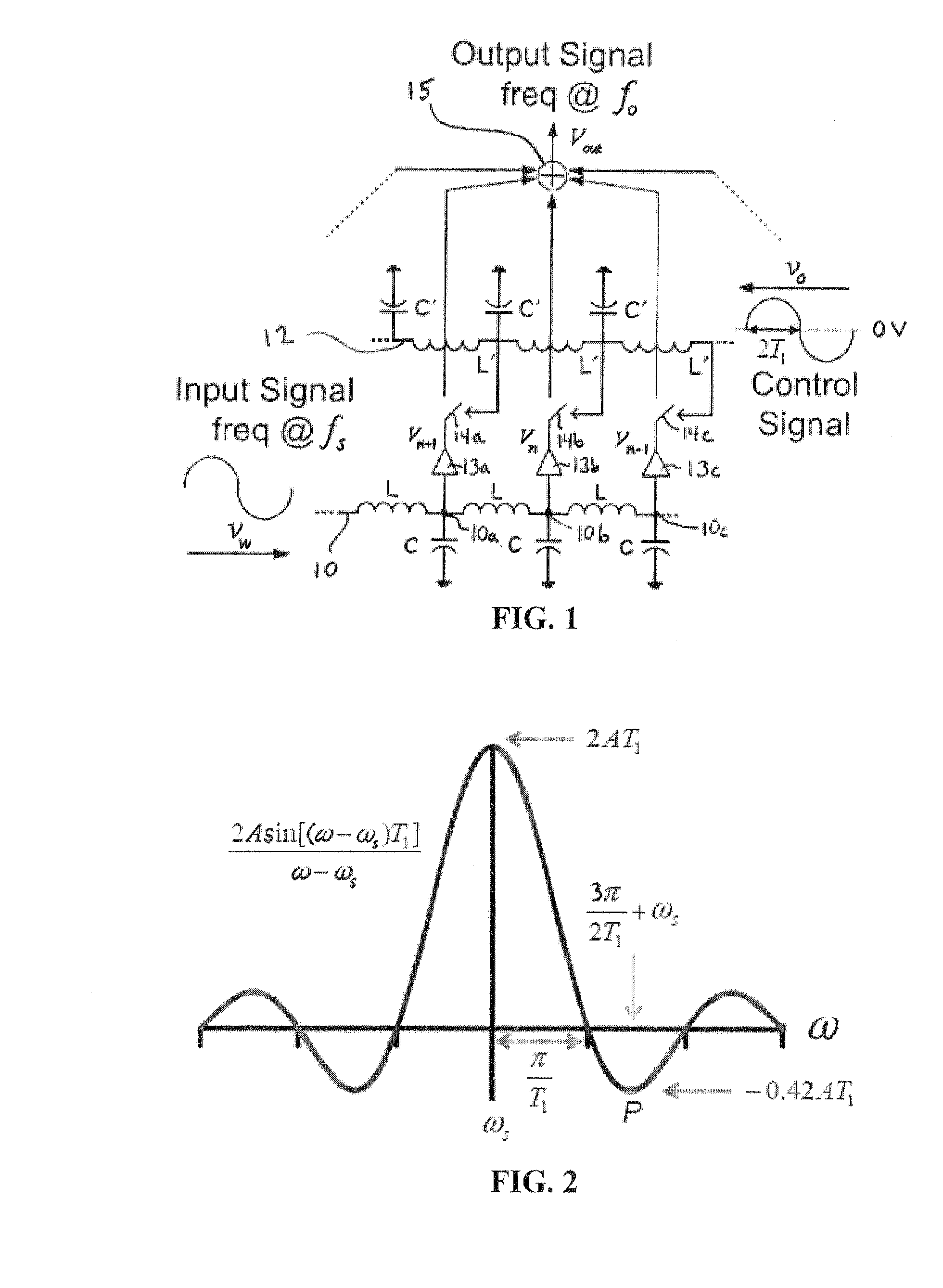
[0048]selecting output frequency ωo=4ωs and using sinusoidal control signal with a zero DC bias.
[0049]For an output frequency at ωo=4ωs and using a sinusoidal control signal with a zero DC bias
(ωc=2π4T1),
ωo can be located anywhere on the curve of FIG. 2 that satisfies Equation 11. From Equation 11, the control signal frequency ωc can be as follows.
ωc=3ωsl.(12)
[0050]There is a trade-off between ωc and the amplitude of the output signal because if ωo is close to the peak in FIG. 2 (e.g., l=1), the output will have high amplitude but ωc would also be high (e.g., ωc=3ωs). To address this issue and also have high ωo with a high amplitude, ωo can be located on the second peak of the Sinc function (point P in FIG. 2). Doing so will result in ωc comparable to ωs, which means that a signal at 4ωs can be generated using two signals at or around ωs.
[0051]In particular, when ωo is located on the second peak
(ωo=3π2T1+ωs):3π2T1+ωs=4ωsωc=ωs.(13)
[0052]This also satisfies Equation 11, and will resul...
example 2
[0060]a sub-harmonic up-converter, up-converting a source signal ωs to around 4ωs.
[0061]A design is implemented to up-convert the source signal to around four times its frequency. To facilitate the measurement and illustrate the concept, the source frequency is selected as fs=9 GHz. Following the analysis presented in Example 1, the output frequency is placed on the second peak (point P) of FIG. 2. In order to distinguish the output signal from the 4th harmonic of the input, the control signal frequency is selected to be fc=10 GHz. Applying these values to Equation 11, results in an output frequency of 3fc+fs=39 GHz, assuming that the switching function is close to the ideal square pulse. To find the response of the switches in FIG. 4, a measurement is obtained of the output power of each section at 9 GHz when the control signal is applied to the gate of M2. FIG. 5 shows a simulation plot of this measurement. When M2 is “on”, L1 and C1 along with M2 resonate at ωs and create a short...
example 3
[0068]Experimental results for the sub-harmonic up-converter, up-converting a source signal ωs to around 4ωs.
[0069]The design described in Example 2 was fabricated in a 0.13 μm digital CMOS process. The die photo is shown in FIG. 7. Two external signal sources were used to apply the source signal (ωs) and the control signal (ωc) to the circuit through GSG probes. Another GSG probe was used to couple the output (3ωc+ωs) to a spectrum analyzer. Bias tees were used to apply DC biases to all three ports. The measured output reflection coefficient, which closely follows the simulation results of FIG. 6, is shown in the plot of FIG. 8. The small amplitude difference between FIG. 8 and FIG. 6 is due to the inaccurate modeling of inductor loss in the simulation.
[0070]FIG. 9 shows the output power at 3fc+fs for different source and control input frequencies. The source signal power and the control signal power are −8 dBm and 10 dBm, respectively. The circuit draws 40 mA from a 1.5 V supply v...
PUM
 Abstract
Description
Claims
Application Information
 - R&D
- Intellectual Property
- Life Sciences
- Materials
- Tech Scout
- Unparalleled Data Quality
- Higher Quality Content
- 60% Fewer Hallucinations
Browse by: Latest US Patents, China's latest patents, Technical Efficacy Thesaurus, Application Domain, Technology Topic, Popular Technical Reports.
© 2025 PatSnap. All rights reserved.Legal|Privacy policy|Modern Slavery Act Transparency Statement|Sitemap|About US| Contact US: help@patsnap.com