
Double offset surgical tool handle assembly having a locking linkage aligned along two different planes

a technology of locking linkage and surgical tool handle, which is applied in the field of surgical tool handle assembly, can solve the problems of difficult to use current solutions without subjecting patients, difficult to clean surgical tool handle with relative ease, and difficult to sterilize the handle, so as to facilitate sterilization, prevent the separation of component parts, and facilitate sterilization

Active Publication Date: 2012-03-22
VIANT AS&O HLDG LLC
View PDF2 Cites 11 Cited by
  • Summary
  • Abstract
  • Description
  • Claims
  • Application Information

AI Technical Summary

Benefits of technology

Facilitates effective sterilization, reduces the risk of disease transmission, and enhances the precision and ease of inserting and orienting prosthetic implants during minimally invasive surgeries, improving patient outcomes by minimizing trauma and recovery time.

Problems solved by technology

Complicated surgical tool handles typically have crevices and recesses that are difficult to clean with relative ease without disassembly into separate component parts.
Tool handles that are not properly cleaned and sterilized increase the risk of disease transfer from patient to patient.
Further, in surgical procedures in which access to the treatment site is limited, it is difficult to use current solutions without subjecting the patient to repeated abrasion and tissue trauma when inserting and extracting surgical instruments.
Additionally, the insertion of a prosthetic implant is often problematic, and the orientation of the implant in a properly prepared recess is often critical to minimize recovery time of the patient.
Still further, once the appropriate position of the tool is selected, it is often difficult to ensure that the position does not change upon insertion of the assembly through the incision.

Method used


Image

  • Double offset surgical tool handle assembly having a locking linkage aligned along two different planes
  • Double offset surgical tool handle assembly having a locking linkage aligned along two different planes
  • Double offset surgical tool handle assembly having a locking linkage aligned along two different planes

Examples


Embodiment Construction

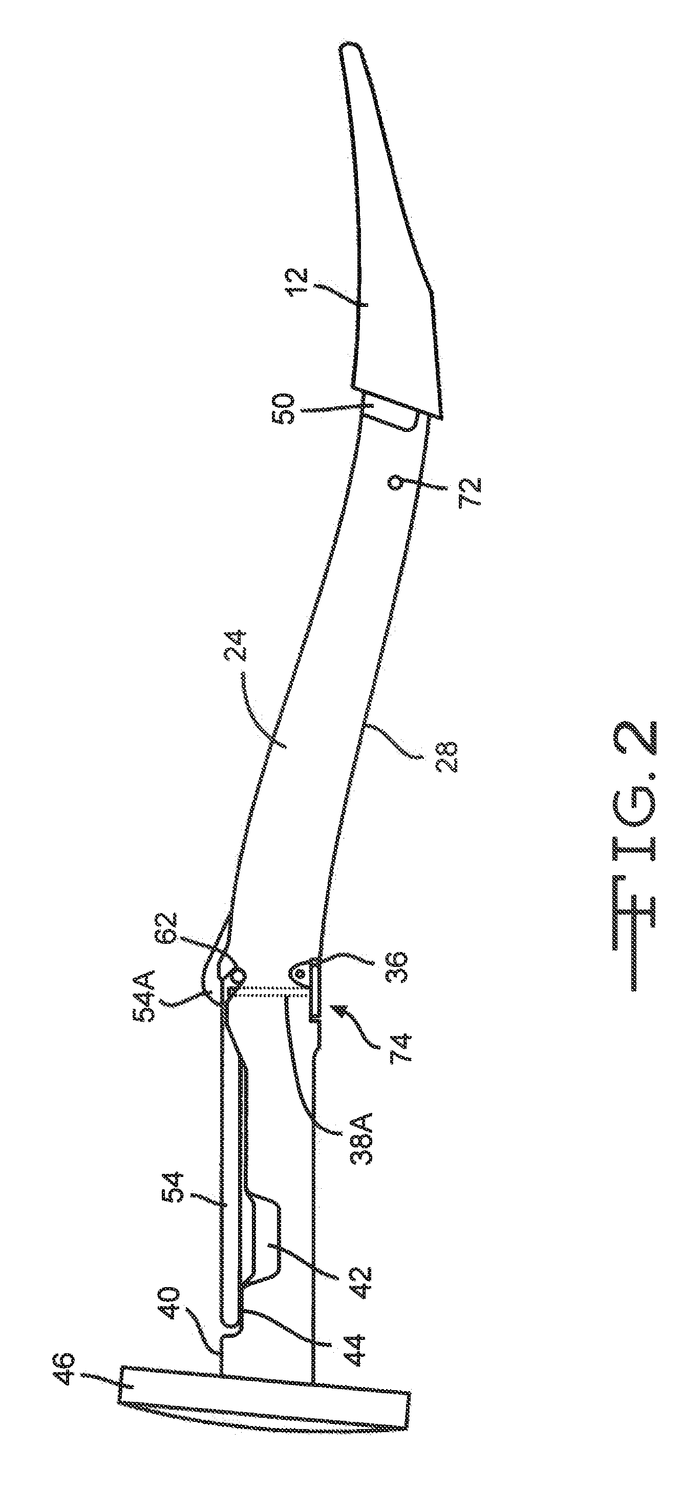
[0018]Turning now to the drawings, FIGS. 1 to 6 illustrate a surgical tool handle assembly 10 according to the present invention. The handle assembly 10 is shown connected to a surgical broach or rasp 12 for performing a minimally invasive hip replacement surgery. Other tools useful with the handle assembly 10 include, but are not limited to, reamers, angled drivers, twist drills, flexible drills, cannulated drills, bayonet drills, bayonet taps, drill guides, adjustable angle drill guides, taps, and cannulated taps.

[0019]The handle assembly 10 generally comprises a linkage train 14 disposed within a housing 16. The housing 16 had a length that extends from a proximal housing section 18 to a distal neck section 20 with an intermediate housing section 22 there between. The intermediate housing section 22 comprises spaced apart right and left side walls 24 and 26 extending upwardly from a bottom wall 28 to an upper opening 30.

[0020]A unique feature of the present handle assembly 10 is ...


PUM


Abstract

A surgical tool handle for releasable connection to a surgical tool is described. The tool handle comprises a housing providing a linkage chamber extending from a proximal housing grip end to a distal housing tool end for receiving a surgical tool. A tool linkage is partially housed within the housing linkage chamber comprising an axial handle region extending along axis A-A and a radiused housing region curving about a focal point. That way, a locking pawl of the tool linkage changes planes from its proximal end to a distal extending hook end. This provides a relatively short connection to a surgical tool that is optimum in the tight space requirements of a minimally invasive hip surgery.

Description

CROSS REFERENCE TO RELATED APPLICATION[0001]This application claims priority to U.S. provisional application Ser. No. 61 / 310,741, filed on Mar. 5, 2010.FIELD OF THE INVENTION[0002]This invention relates to surgical tools for aiding in the installation of orthopedic prostheses in patients. More particularly, the present invention relates to an easily sterilizable handle assembly for use with a surgical tool in preparing a bone site, and for use in installing a prosthesis in the bone.BACKGROUND OF THE INVENTION[0003]Complicated surgical tool handles typically have crevices and recesses that are difficult to clean with relative ease without disassembly into separate component parts. Tool handles that are not properly cleaned and sterilized increase the risk of disease transfer from patient to patient. This is especially true following the emergence of certain “prions” that are not killed by normal hospital sterilization. A prion is a type of infectious agent made only of protein.[0004]...

Claims


Application Information

Patent Timeline
Patent Type & Authority Applications(United States)
IPC IPC(8): A61B17/00
CPCA61B17/162A61B17/1659A61B2017/00473A61B2017/0046A61B17/1668
Inventor BURGI, JONAS
Owner VIANT AS&O HLDG LLC
Learn More