Machine tool including tool radius adjusting device

a technology of tool radius and adjustment device, which is applied in the field of machine tools, can solve the problems of difficult carrying and fitting the heavy boring holder, and the large volume of the boring holder having an adjustable tool radius, so as to suppress the increase in the time for changing the tool, suppress the situation, and suppress the effect of the increase in the machining cycle tim

Active Publication Date: 2012-03-08
JTEKT CORP
View PDF7 Cites 10 Cited by
  • Summary
  • Abstract
  • Description
  • Claims
  • Application Information

AI Technical Summary

Benefits of technology

[0008]According to a feature of an example of the invention, in a tool magazine, a tool radius adjustment index position and a tool change index position are set to different positions. Further, a tool radius adjusting device is able to execute an operation for adjusting the tool radius of the boring holder in parallel with execution of a machining program for executing an operation of the spindle head and an operation of a tool changer. In addition, a carrier control unit determines whether a tool changing process is being executed by the tool changer, and allows a carrier device to execute an operation for picking the boring holder out from the tool magazine and an operation for returning the boring holder, of which the tool radius has been adjusted, to the tool magazine when the tool changing process is not being executed. Thus, it is possible to execute an operation of the tool radius adjusting device and an operation of the carrier device without exerting influence on a process of a machining program. Accordingly, it is possible to suppress an increase in a machining cycle time even if the tool radius of the boring holder is adjusted.
[0009]According to another feature of an example of the invention, when a duration of time before execution of a tool changing process is started is equal to or longer than a predetermined duration of time, the operation of the carrier device is executed. Accordingly, it is possible to suppress occurrence of the situation where the tool is changed by the tool changer while the carrier device is executing the operation for picking the boring holder out from the tool magazine or the operation for returning the boring holder, of which the tool radius has been adjusted, to the tool magazine. That is, it is possible to execute the operation of the carrier device without exerting influence on a tool changing operation executed by the tool changer. As a result, it is possible to suppress an increase in time for changing the tools, which will exert influence on the machining cycle time.
[0010]According to a further feature of an example of the invention, when the boring holder is arranged at the tool radius adjusting device, the tool axis direction of the boring holder coincides with the vertical direction. Thus, an operator is able to place a new boring holder in the tool magazine by arranging the new boring holder at the tool radius adjusting device and operating the carrier device. Especially, the mass of the boring holder having an adjustable tool radius may be heavy. Therefore, it is not easy to carry and fit the heavy boring holder such that the tool axis direction of the boring holder coincides with horizontal direction, in order to directly place the boring holder in the tool magazine. In contrast to this, even if the boring holder has a heavy mass, it is relatively easy to carry and fit the boring holder such that the tool axis direction of the boring holder coincides with the vertical direction. That is, it is possible to more easily place the heavy boring holder in the tool magazine if the boring holder is placed in the tool magazine via the tool radius adjusting device.

Problems solved by technology

Especially, the mass of the boring holder having an adjustable tool radius may be heavy.
Therefore, it is not easy to carry and fit the heavy boring holder such that the tool axis direction of the boring holder coincides with horizontal direction, in order to directly place the boring holder in the tool magazine.

Method used


Image

  • Machine tool including tool radius adjusting device
  • Machine tool including tool radius adjusting device
  • Machine tool including tool radius adjusting device

Examples


Embodiment Construction

[0035]Hereinafter, embodiments of the invention will be described with reference to the accompanying drawings.

[0036]Construction of Boring Holder

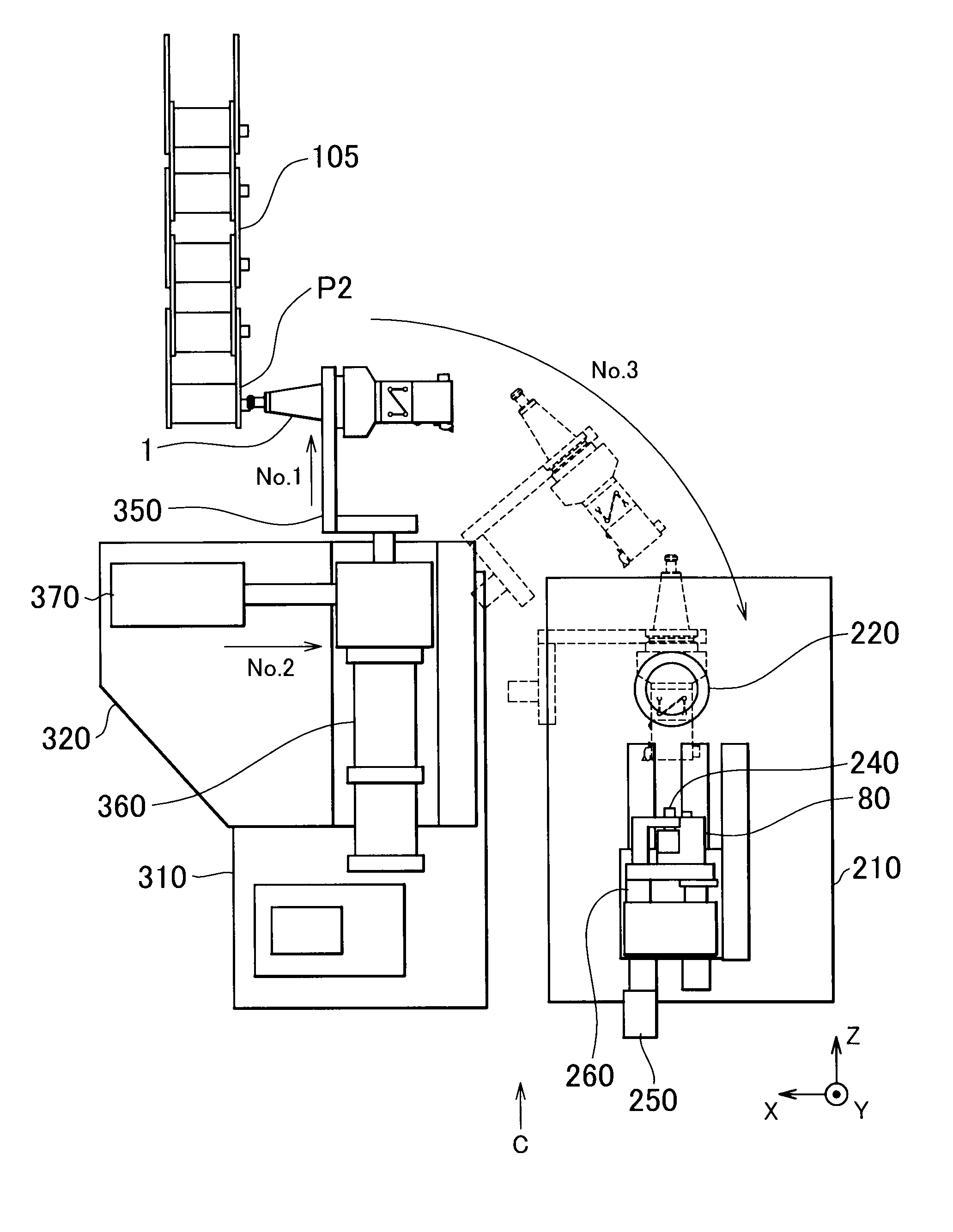
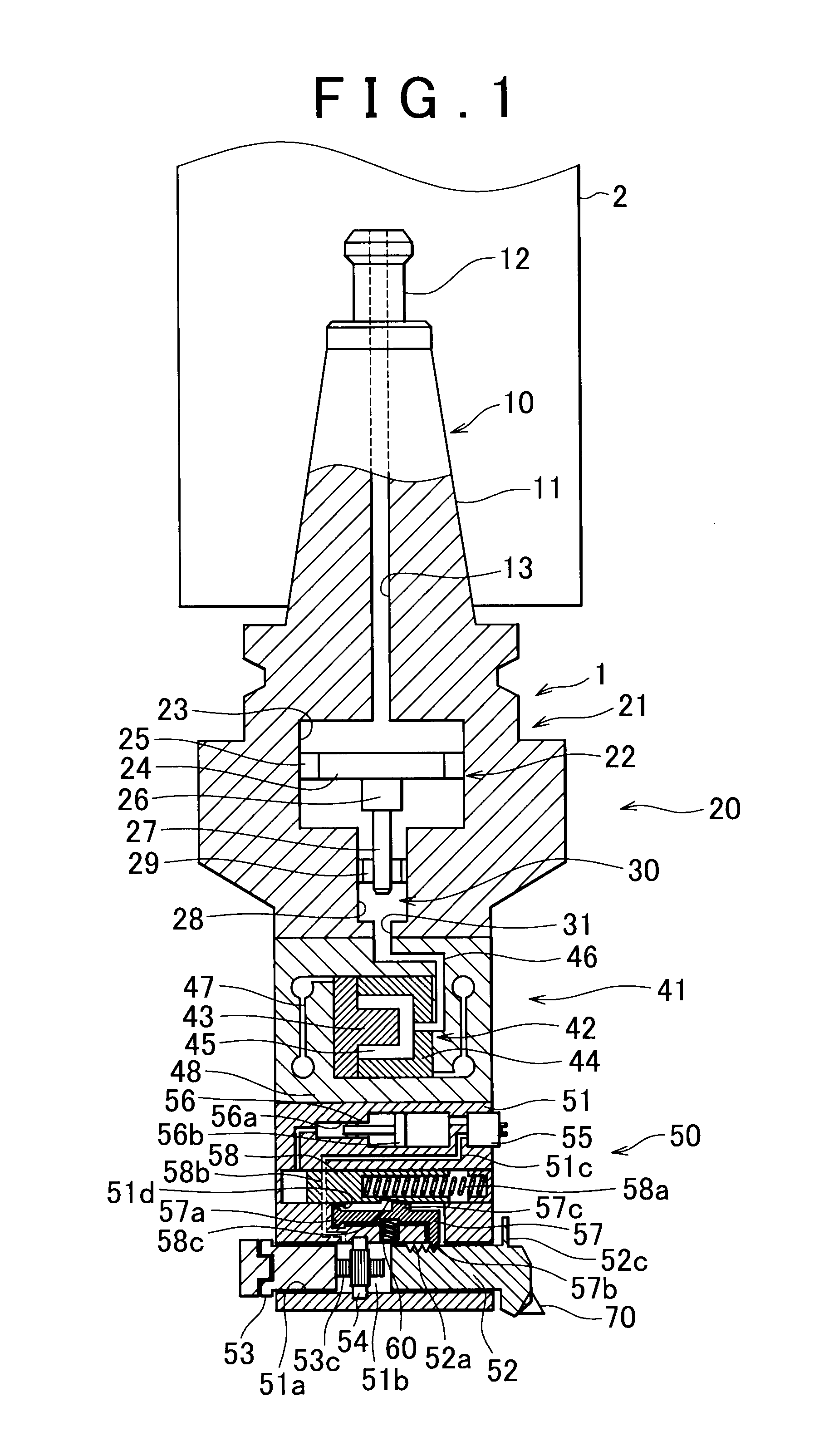
[0037]The construction of a boring holder 1 in a first embodiment will be described with reference to FIGS. 1-3. As shown in FIG. 1, the boring holder 1 is a tool assembly which is held in a tool spindle 2 being rotatable about its axis for machining bores, recesses and the like in a workpiece, and is capable of adjusting its tool radius. In each of the figures, a tool spindle 2 side of the boring holder 1 will be referred to as base end or base end side, whereas a side with a cutting blade 70 thereon of the boring holder 1 will be referred to as distal end or distal end side.

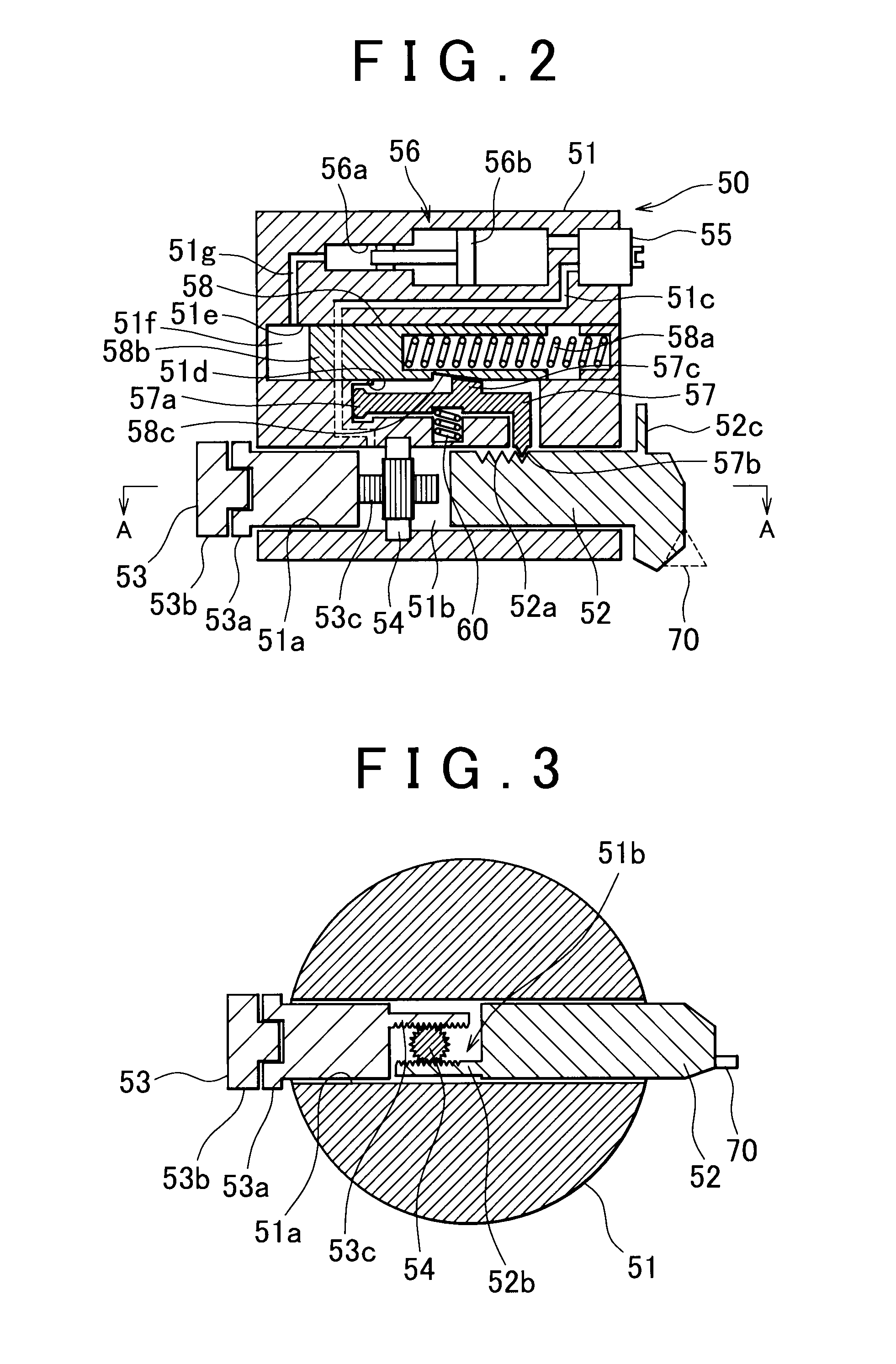
[0038]The boring holder 1 is provided with a holder portion 10, a fine motion adjusting mechanism 20, a coarse motion adjusting mechanism 50, and the cutting blade 70. The holder portion 10, the fine motion adjusting mechanism 20 and the coarse motion adjusting mechani...


PUM

PropertyMeasurementUnit
Radiusaaaaaaaaaa
Timeaaaaaaaaaa

Abstract

A tool radius adjusting device executes an operation for adjusting the tool radius of a boring holder in parallel with execution of a machining program for executing an operation of a spindle head and an operation of a tool changer. A carrier control unit determines whether the tool changer is executing a tool changing process. When the tool changing process is not being executed, the carrier control unit allows the carrier device to execute an operation for picking the boring holder out from the tool magazine and an operation for returning the boring holder, of which the tool radius has been adjusted, to the tool magazine.

Description

INCORPORATION BY REFERENCE[0001]This application claims priority to Japanese Patent Application No. 2010-199116 filed on Sep. 6, 2010 the disclosure of which, including the specification, drawings and abstract, is incorporated herein by reference in its entirety.BACKGROUND OF THE INVENTION[0002]1. Field of the Invention[0003]The invention relates to a machine tool that includes a tool radius adjusting device that adjusts a tool radius of a boring holder, the tool radius being adjustable.[0004]2. Description of Related Art[0005]For example, Japanese Patent Application Publication No. 2007-283469 (JP 2007-283469 A) describes a conventional boring holder that has an adjustable tool radius. The tool radius of the boring holder is adjusted with the boring holder fitted to a tool spindle of a machine tool, for example, a machining center.[0006]However, if the tool radius is adjusted with the boring holder fitted to the tool spindle of the machine tool, it is not possible to machine a work...

Claims


Application Information

Patent Timeline
IPC IPC(8): B23Q3/157
CPCB23B29/03421B23B29/03425B23Q3/15713B23Q3/1574Y10T408/76Y10T483/15Y10T408/85843Y10T408/856B23B29/03432Y10T483/12Y10T483/13Y10T483/1738
Inventor NAKAMURA, EIJIKADOTA, AKIHIKOYOKOYAMA, TAKASHI
Owner JTEKT CORP
Why Eureka
Try Eureka