Fluted sprocket/cog bore for reduced machining cycle times and reduced tool wear

a technology of sprocket/cog bore and rotary member, which is applied in the direction of transportation and packaging, hoisting equipment, other domestic articles, etc., can solve the problems of increasing the load and wear of the cutting tool element on the manufacturing equipment, and achieves the reduction of the machining cycle time of the bore forming machining operation, the effect of increasing the flushing of coolan

Inactive Publication Date: 2015-10-01
BORGWARNER INC
View PDF37 Cites 1 Cited by
  • Summary
  • Abstract
  • Description
  • Claims
  • Application Information

AI Technical Summary

Benefits of technology

The patent aims to reduce the load on manufacturing equipment, increase coolant flushing, and reduce cutting tool wear while forming a bore in a rotary member. This is achieved by introducing fluting on the inner surface of the rotary member, which serves to reduce material to be removed in finishing operations while still providing centering of the member with respect to a shaft. The fluted bore can contact the shaft and provide sufficient surface contact to keep it in place. The patent is useful in various applications such as timing systems, alternator pulleys, power steering pulleys, and timing system cogs.

Problems solved by technology

The finishing operation requires machining along an entire internal circumference of the bore to be provided in the rotary member, which is a very time consuming machining operation and subjects the manufacturing equipment to increased load and wear on the cutting tool element.

Method used


Image

  • Fluted sprocket/cog bore for reduced machining cycle times and reduced tool wear
  • Fluted sprocket/cog bore for reduced machining cycle times and reduced tool wear

Examples


Embodiment Construction

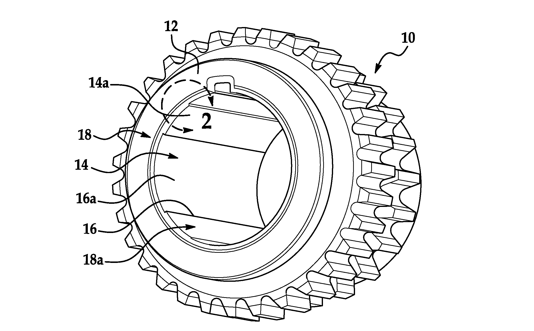
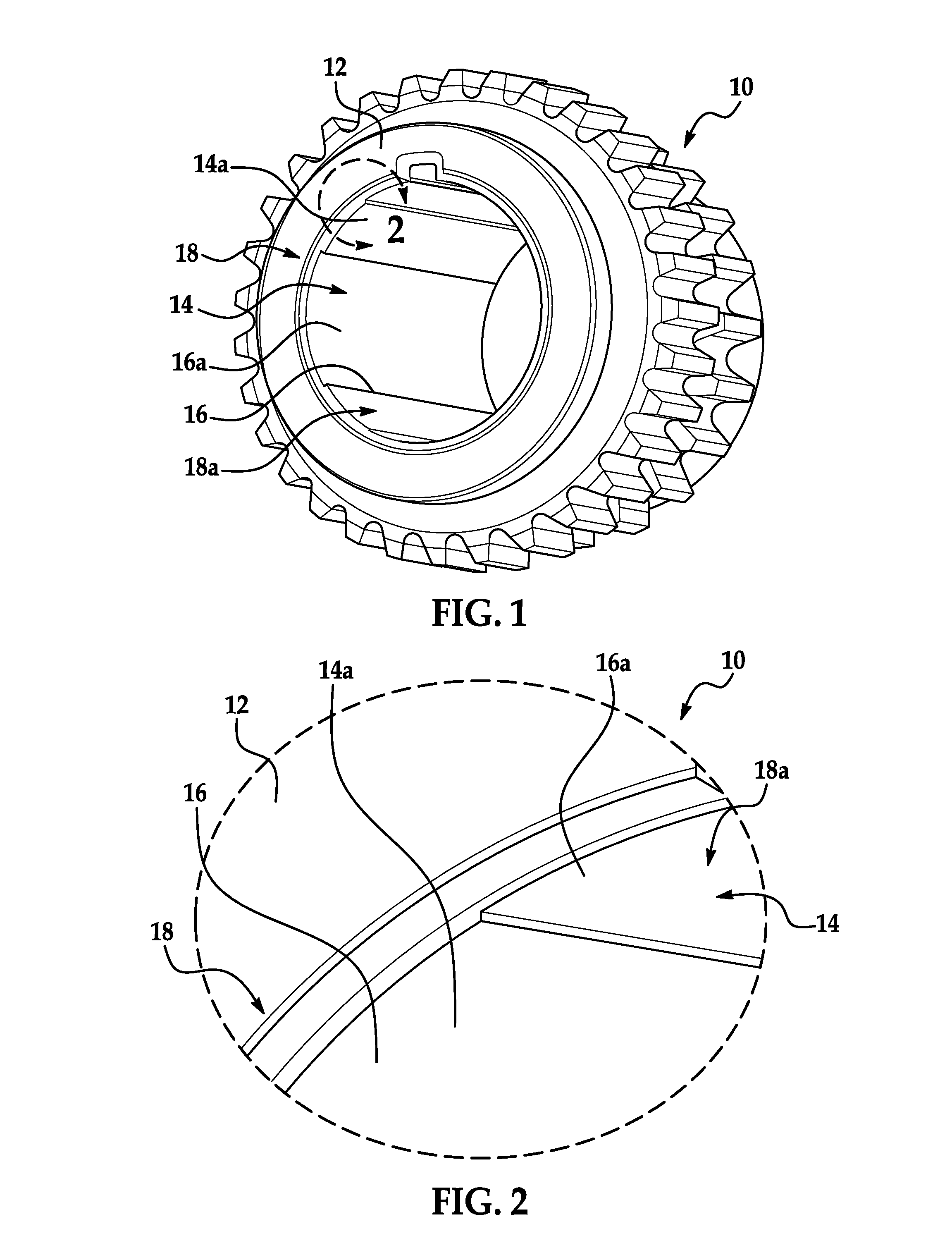
[0012]Referring now to FIG. 1, by way of example and not limitation, a rotary member 10, sometimes referred to herein as a sprocket, gear, pulley or cog, for an endless loop power transmission system is illustrated having a hub 12. The hub 12 includes a plurality of radially inwardly and axially extending flutes 14, sometimes referred to herein as raised flutes, formed along an inner circumferential surface 16 of an aperture 18 and extending axially through the hub 12 of the rotary member 10. The raised flutes 14 reduce an amount of material stock to be removed during finishing machining operations, while providing a finished surface after machining for centering the sprocket 10 on a shaft (not shown).

[0013]A rotary member 10 of an endless loop power transmission system includes a hub 12 for centered connection to a shaft (not shown). The hub 12 has an inner circumferential surface 16 defining a central aperture 18 extending therethrough with a plurality of flutes 14 on the inner ci...


PUM

PropertyMeasurementUnit
circumferential surface areasaaaaaaaaaa
surface areasaaaaaaaaaa
areasaaaaaaaaaa

Abstract

A rotary member (10) of an endless loop power transmission system can have a hub (12) for a centered connection to a shaft. The hub (12) can have a central aperture (18) extending therethrough and a plurality of radially inwardly projecting and axially extending flutes (14) formed on an inner circumferential surface (16) of the central aperture (18) defining reduced circumferential surface areas (16a) for machining a central bore (18a) through the hub (12). An interrupted finishing machining cut along the reduced circumferential surface areas (16a) of the central aperture (18) provides increased coolant flushing, while reducing finishing machining cycle times, and reducing load and wear on a bore cutter.

Description

FIELD OF THE INVENTION[0001]The present invention relates to a fluted rotary member, such as a sprocket, gear, pulley, or cog with a machined bore, where the fluted surface of the rotary member reduces material to be removed in subsequent finishing operations.BACKGROUND[0002]It is generally know to provide a rotary member, such as a sprocket, gear, pulley, or cog by compacting, forging, molding, and stamping manufacturing techniques. These known rotary member manufacturing techniques provide unfinished bores that require finishing operations to provide a precision surface for contact with a shaft. The finishing operation requires machining along an entire internal circumference of the bore to be provided in the rotary member, which is a very time consuming machining operation and subjects the manufacturing equipment to increased load and wear on the cutting tool element.SUMMARY[0003]It would be desirable to reduce the load on manufacturing equipment during the bore forming machining...

Claims


Application Information

Patent Timeline
Patent Type & Authority Applications(United States)
IPC IPC(8): F16H55/30F16H55/36B21K1/30
CPCF16H55/30F16H55/36B21K1/30B21K1/40F16H55/17Y10T29/49467
Inventor BLACKMUR, SHAWN J.
Owner BORGWARNER INC
Why Eureka
Try Eureka