Mesa-Type At-Cut Quartz-Crystal Vibrating Piece and Quartz-Crystal Device
a technology of quartz crystal and at-cut quartz, which is applied in piezoelectric/electrostrictive/magnetostrictive devices, piezoelectric/electrostriction/magnetostriction machines, electrical apparatuses, etc., can solve the problems of at-cut quartz crystal vibrating piece degradation and difficult conduction, so as to prevent the degradation of its characteristics and reduce the rejection rate
- Summary
- Abstract
- Description
- Claims
- Application Information
AI Technical Summary
Benefits of technology
Problems solved by technology
Method used
Image

Examples
first embodiment
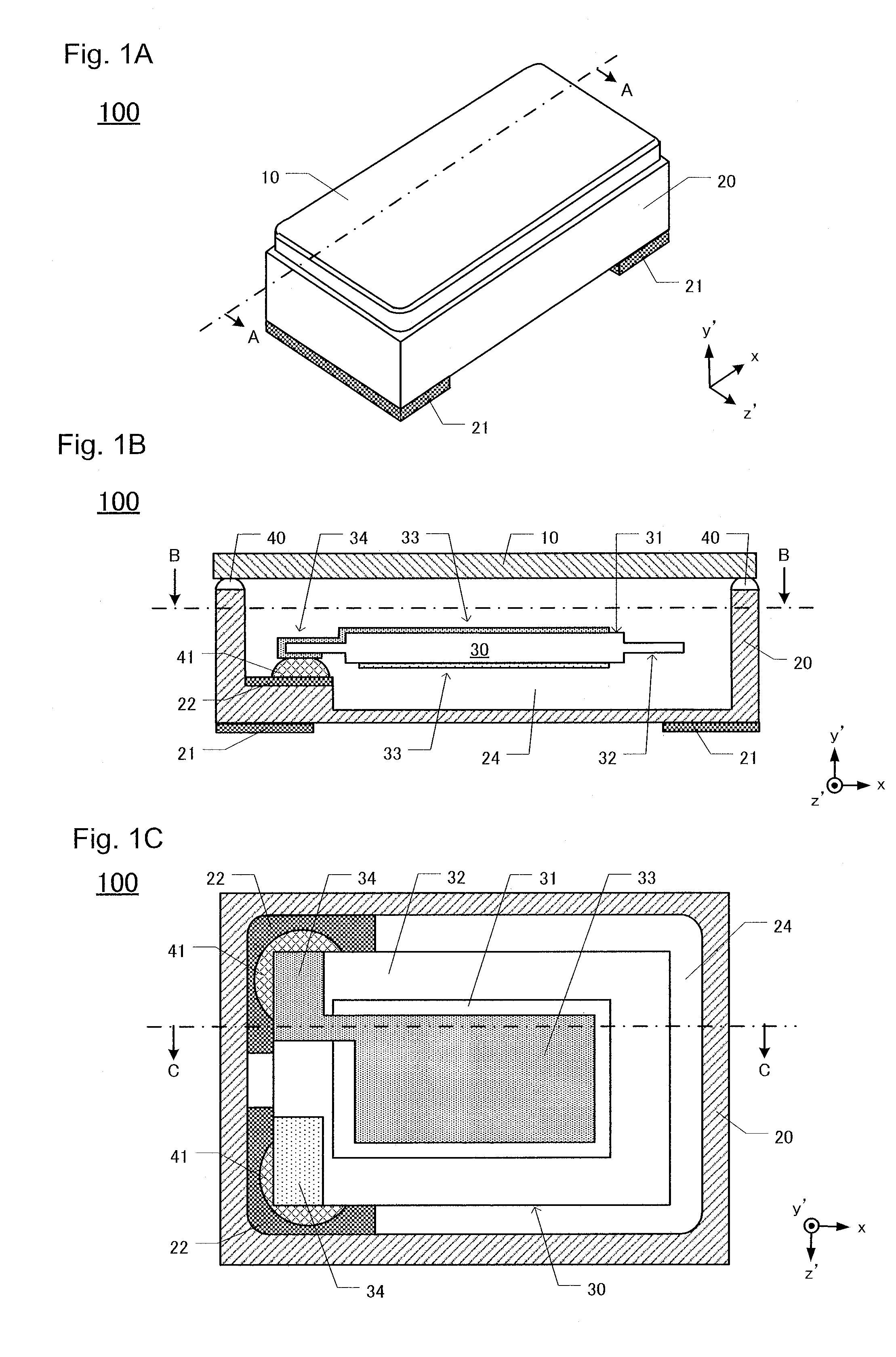
[0035]100>
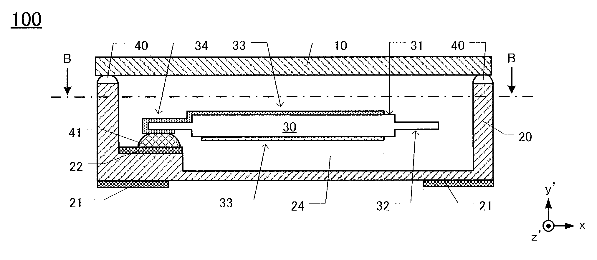
[0036]FIG. 1A is a perspective view of the quartz-crystal device 100. The quartz-crystal device 100 is constituted of the lid 10, base 20 and AT-cut quartz-crystal vibrating piece 30 mounted onto the base 20 (refer to FIG. 1 B). The AT-cut quartz-crystal vibrating piece has a principal surface that is inclined, with respect to the Y-axis of the crystal axes (XYZ), from the Z-axis to the Y-axis direction by 35° 15′, with the X-axis as a center. Therefore, the quartz-crystal device 100 is described below by designating a longitudinal direction thereof as the x-axis direction, designating the short-side direction as the z′-axis direction, and thickness direction thereof as the y-axis direction. In this explanation below, inclination to the y′-axis is denoted as +y-′axis and declination to the y′-axis is denoted as −y′-axis.
[0037]A cavity 24 is formed on the inner side of the base 20 (refer to FIG. 1B), and an AT-cut quartz-crystal vibrating piece 30 is situated onto the cavit...
second embodiment
[0064]The AT-cut quartz-crystal vibrating piece 30 can be surrounded by an outer frame. A quartz-crystal device 200 comprising the AT-cut quartz-crystal vibrating piece surrounded by the outer frame is explained hereafter.
[0065]200>
[0066]FIG. 7A is an exploded view of the quartz-crystal device 200. The quartz-crystal device 200 comprises a lid 210, an AT-cut quartz-crystal vibrating piece 230 and a base 220. On the quartz-crystal device 200, the lid 210 is disposed on the upper portion, the base 220 is disposed on the lower portion, and the AT-cut quartz-crystal vibrating piece 230 is sandwiched between the lid 210 and base 220. The external electrodes 221 are disposed on a lower surface of the base 220. The lid 210 and base 220 are fabricated from a glass or quartz-crystal material.
[0067]FIG. 7B is a cross-section of FIG. 7A along E-E line. On the AT-cut quartz-crystal vibrating piece 230, an excitation unit 231 and a peripheral region 232 are formed, in which the peripheral region...
PUM
 Abstract
Description
Claims
Application Information
 - R&D
- Intellectual Property
- Life Sciences
- Materials
- Tech Scout
- Unparalleled Data Quality
- Higher Quality Content
- 60% Fewer Hallucinations
Browse by: Latest US Patents, China's latest patents, Technical Efficacy Thesaurus, Application Domain, Technology Topic, Popular Technical Reports.
© 2025 PatSnap. All rights reserved.Legal|Privacy policy|Modern Slavery Act Transparency Statement|Sitemap|About US| Contact US: help@patsnap.com