
Method and apparatus for time-domain reverse-time migration with source estimation

a source estimation and source technology, applied in the field of seismic imaging methods, can solve the problems of limiting not easy to accurately detect the waveform of a source, etc., and achieve the effect of improving the resolution of reverse-time migration

Inactive Publication Date: 2012-03-01
SEOUL NAT UNIV R&DB FOUND
View PDF5 Cites 24 Cited by
  • Summary
  • Abstract
  • Description
  • Claims
  • Application Information

AI Technical Summary

Benefits of technology

"The patent describes a technique for improving the resolution of reverse-time migration through source estimation in the time domain. The technique involves estimating sources by solving a matrix equation and performing reverse-time migration in the time domain. The method was tested using a BP model and showed that the final images obtained using the transmission waveform inversion algorithm showed significantly clearer reflection surfaces, particularly in the halite structure. The technical effect of this technique is improved resolution in reverse-time migration."

Problems solved by technology

Various sources were used in seismic exploration, but it was not easy to accurately detect the waveforms of a source since there are non-linear wave propagation, noise near the source and coupling between the source and receivers, etc.
Accordingly, the existing reverse-time migration failed to reflect an accurate source, which became a factor limiting the resolution of reverse-time migration.

Method used


Image

  • Method and apparatus for time-domain reverse-time migration with source estimation
  • Method and apparatus for time-domain reverse-time migration with source estimation
  • Method and apparatus for time-domain reverse-time migration with source estimation

Examples


Embodiment Construction

[0019]The following description is provided to assist the reader in gaining a comprehensive understanding of the methods, apparatuses, and / or systems described herein. Accordingly, various changes, modifications, and equivalents of the methods, apparatuses, and / or systems described herein will be suggested to those of ordinary skill in the art. Also, descriptions of well-known functions and constructions may be omitted for increased clarity and conciseness.

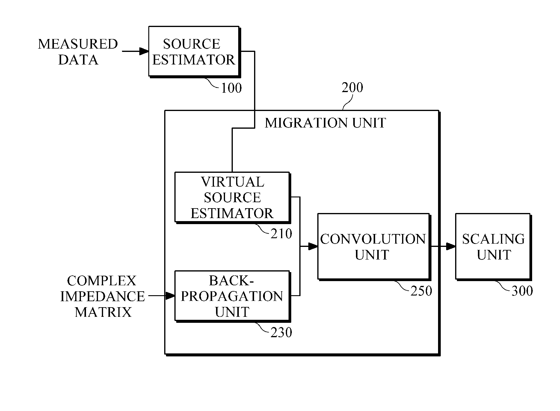
[0020]FIG. 1 is a diagram illustrating an example of a reverse-time migration apparatus. Referring to FIG. 1, the reverse-time migration apparatus includes a source estimator 100 that obtains transmission waveforms from measured data on receivers to estimate sources, and a migration unit 200 that receives information about the estimated sources to perform reverse-time migration in the time domain.

[0021]According to an example, the migration unit 200 includes a back-propagation unit 230 that back-propagates the measured data on the...


PUM


Abstract

Provided is seismic imaging, particularly, a time-domain reverse-time migration technique for generating a real subsurface image from modeling parameters calculated through waveform inversion, etc. A reverse-time migration apparatus according to an example includes a source estimator configured to estimate sources by obtaining transmission waveforms from data measured by a plurality of receivers, through waveform inversion, and a migration unit configured to receive information about the estimated sources, and to perform reverse-time migration in the time domain. The source estimator estimates sources, by solving first-order matrix equation including a Toeplitz matrix composed of autocorrelation values of the Green's function, and a cross-correlation matrix of measured data and the Green's function, through Levinson Recursion. In more detail, the migration unit includes a back-propagation unit configured to back-propagate the measured data; a virtual source estimator configured to estimate virtual sources from the sources estimated by the source estimator; and a convolution unit that configured to convolve the back-propagated data with the virtual sources and output the results of the convolution.

Description

CROSS-REFERENCE TO RELATED APPLICATION[0001]This application claims the benefit under 35 U.S.C. §119(a) of a Korean Patent Application No. 10-2010-0082733, filed on Aug. 26, 2010, the entire disclosure of which is incorporated herein by reference for all purposes.BACKGROUND[0002]1. Field[0003]The following description relates to a seismic imaging method, and more particularly, to a reverse-time migration for generating a real subsurface image from modeling parameters calculated by waveform inversion, etc.[0004]2. Description of the Related Art[0005]A two-way migration method requires significantly more computational resources than a one-way migration method. However, since the two-way migration method has substantially no dip limitation as well as processing multiarrivals, the two-way migration method allows seismic imaging regardless of the inclination of a reflection surface and also can preserve the real amplitudes of seismic wavefields. For these reasons, the two-way migration m...

Claims


Application Information

Patent Timeline
Patent Type & Authority Applications(United States)
IPC IPC(8): G01V1/36
CPCG01V1/28G01V2210/51G01V2210/67G01V2210/679G01V2210/675
Inventor SHIN, CHANGSOO
Owner SEOUL NAT UNIV R&DB FOUND
Learn More