
Source-collector module with GIC mirror and xenon ice EUV LPP target system

a source-collector module and target system technology, applied in the field of grainincidence collectors, can solve the problems of inability to use in conjunction with debris mitigation tools, unfavorable euv lithography systems, and high cos

Inactive Publication Date: 2012-03-01
MEDIA LARIO SRL
View PDF4 Cites 39 Cited by
  • Summary
  • Abstract
  • Description
  • Claims
  • Application Information

AI Technical Summary

Problems solved by technology

However, a commercially viable EUV lithography system requires a SOCOMO that has a long lifetime.
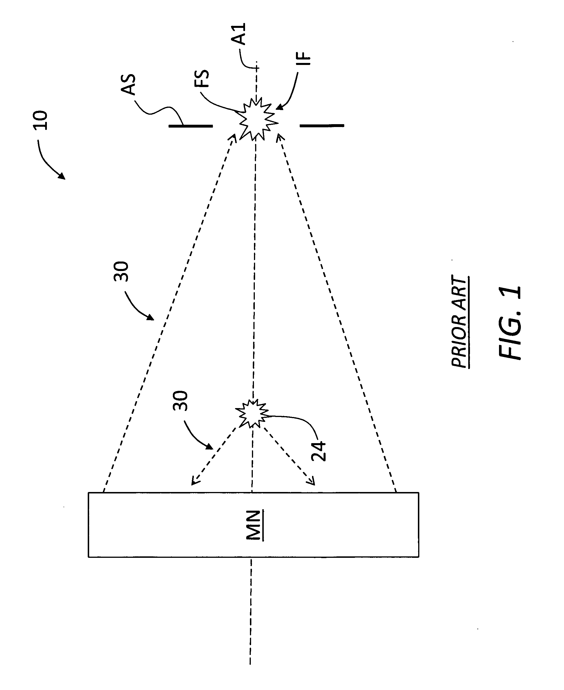
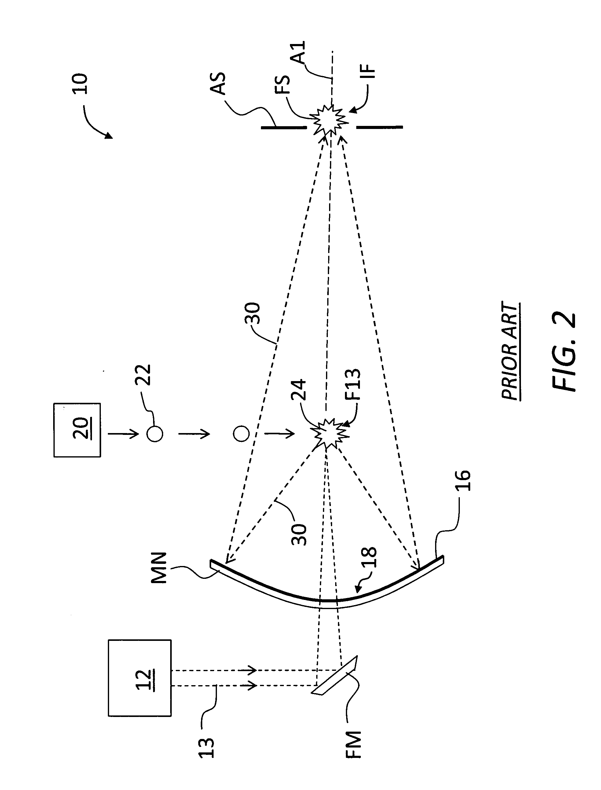
Unfortunately, the proximity of the NIC mirror surface 16 and the multilayer coatings 18 thereon to LPP 24, combined with the substantially normally incident nature of the radiation collection process, makes it highly unlikely that the multilayer coating 18 will remain undamaged for any reasonable length of time under typical EUV-based semiconductor manufacturing conditions.
A further drawback of the LPP-NIC SOCOMO 10 is that it cannot be used in conjunction with a debris mitigation tool based on a plurality of radial lamellas through which a gas is flowed to effectively stop ions and neutrals atoms emitted from the LPP 24 from reaching NIC mirror MN.
Multilayer coating 18 is also likely to have its performance significantly reduced by the build-up of Sn, which significantly absorbs the incident and reflected EUV radiation, thereby reducing the reflective efficiency of the multilayer coated ellipsoidal mirror.
While a variety of fixes have been proposed to mitigate the above-identified problems with LPP-NIC SOCOMO 10, they all add substantial cost and complexity to the SOCOMO, to the point where it becomes increasingly unrealistic to include it in a commercially viable EUV lithography system.
Moreover, the Sn droplet LPP EUV light source is a complex and expensive part of the SOCOMO.

Method used


Image

  • Source-collector module with GIC mirror and xenon ice EUV LPP target system
  • Source-collector module with GIC mirror and xenon ice EUV LPP target system
  • Source-collector module with GIC mirror and xenon ice EUV LPP target system

Examples


example gic

Mirror for LPP-GIC SOCOMO

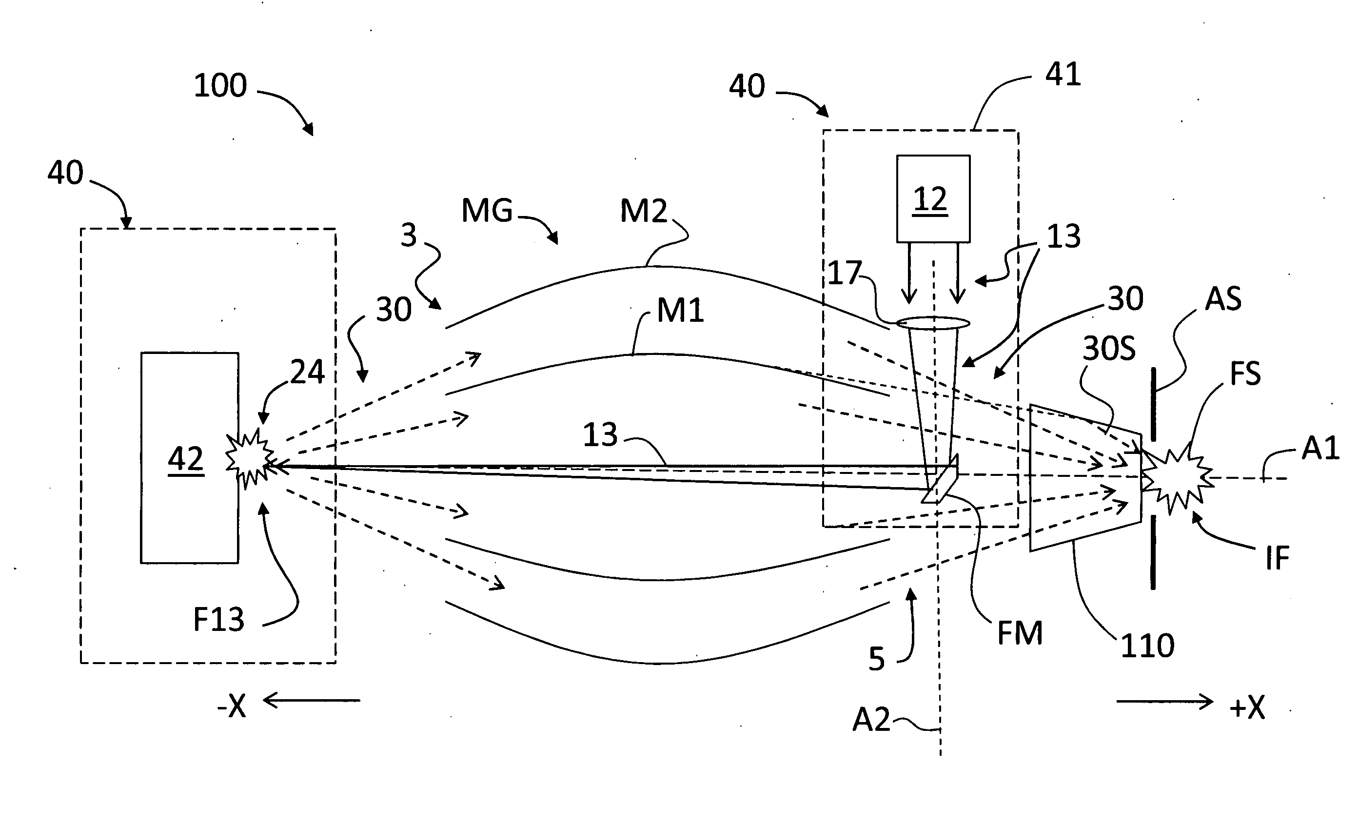
[0058]FIG. 7 is a schematic side view of a portion of an example GIC mirror MG for use in LPP-GIC SOCOMO 10. By way of example, the optical design of GIC mirror MG of FIG. 7 actually consists of eight nested GIC shells 250 with cylindrical symmetry around the optical axis A1, as shown in FIG. 8. To minimize the number of GIC shells 250, in the present example the first three innermost GIC shells are elliptical, whereas the five outermost GIC shells are based on an off-axis double-reflection design having elliptical and hyperbolic cross sections, such as described in European Patent Application Publication No. EP1901126A1, entitled “A collector optical system,” which application is incorporated by reference herein. FIG. 7 shows two of the outermost GIC shells 250 having an elliptical section 250E and a hyperboloidal section 250H. FIG. 7 also shows the source focus SF, the virtual common focus CF, and the intermediate focus IF, as well as the axes AE and AH fo...


PUM


Abstract

A source-collector module (SOCOMO) for generating a laser-produced plasma (LPP) that emits EUV radiation, and a grazing-incidence collector (GIC) mirror arranged relative to the LPP and having an input end and an output end. The LPP is formed using an LPP target system having a light source portion and a target portion, wherein a pulsed laser beam from the light source portion irradiates Xenon ice provided by the target portion to an irradiation location. The GIC mirror is arranged relative to the LPP to receive the EUV radiation at its input end and focus the received EUV radiation at an intermediate focus adjacent the output end. A radiation collection enhancement device having at least one funnel element may be used to increase the amount of EUV radiation provided to the intermediate focus and / or directed to a downstream illuminator. An EUV lithography system that utilizes the SOCOMO is also disclosed.

Description

FIELD[0001]The present disclosure relates generally to grazing-incidence collectors (GICs), and in particular to a source-collector module for use in an extreme ultraviolet (EUV) lithography system that employs a laser-produced plasma (LPP) target system that uses Xenon ice to generate EUV radiation.BACKGROUND ART[0002]Laser-produced plasmas (LPPs) are formed in one example by irradiating Sn droplets with a focused laser beam. Because such LPPs can radiate in the extreme ultraviolet (EUV) range of the electromagnetic spectrum, they are considered to be a promising EUV radiation source for EUV lithography systems.[0003]FIG. 1 is a schematic diagram of a generalized configuration for a prior art LPP-based source-collector module (“SOCOMO”) 10 that uses a normal-incidence collector (“NIC”) mirror MN, while FIG. 2 is a more specific example configuration of the “LPP-NIC” SOCOMO 10 of FIG. 1. The LPP-NIC SOCOMO 10 includes a high-power laser 12 that generates a high-power, high-repetitio...

Claims


Application Information

Patent Timeline
IPC IPC(8): G03B27/52H05G2/00
CPCB82Y10/00G02B5/0891G21K1/067G21K2201/061G03F7/70166G21K2201/067H05G2/008H05G2/006G03F7/70033G21K2201/064
Inventor LEVESQUE, RICHARD A.CEGLIO, NATALE M.NOCERINO, GIOVANNIZOCCHI, FABIO
Owner MEDIA LARIO SRL
Learn More