
Spring clamp for an air filter housing

Active Publication Date: 2012-03-01
FORD GLOBAL TECH LLC
View PDF6 Cites 22 Cited by
  • Summary
  • Abstract
  • Description
  • Claims
  • Application Information

AI Technical Summary

Benefits of technology

[0004]The inventors herein recognize potential issues with such a spring clamp. As one example, in the previously described spring clamp the majority of elastic deformation is absorbed in a relatively small region of the spring clip, located around the joint. As the lever is also located at the joint, force is additionally applied directly to the joint while moving the spring lever into the engaged position. Over time, the joint may become permanently deformed or break. Deformation or breakage of the spring clamp may eliminate the compressive load provided to the casings and the seal is decreased. If the compressive load is insufficient, unfiltered air will enter through the seal and particulate matter may enter engine cylinders, causing mechanical wear and oil contamination.
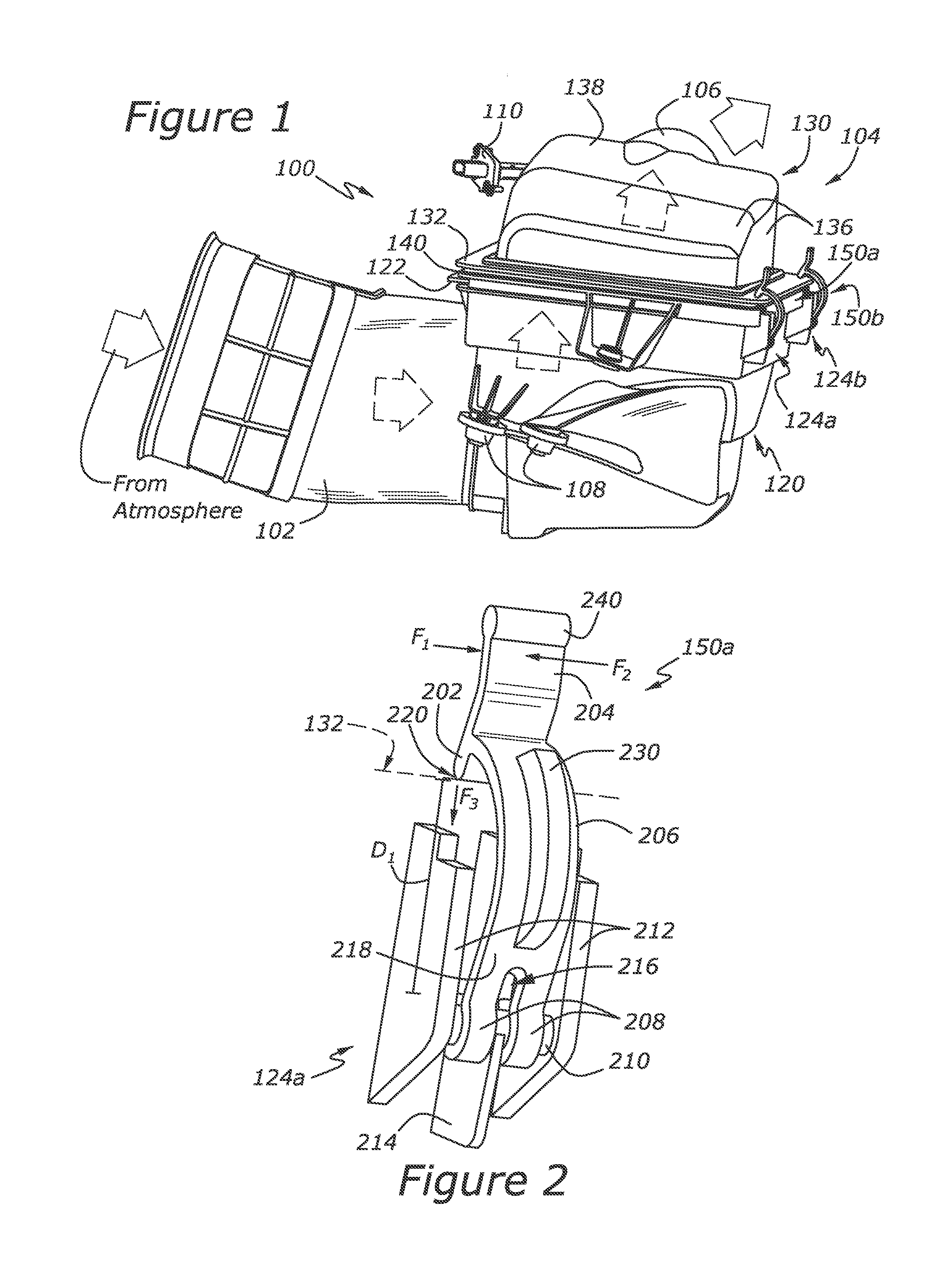
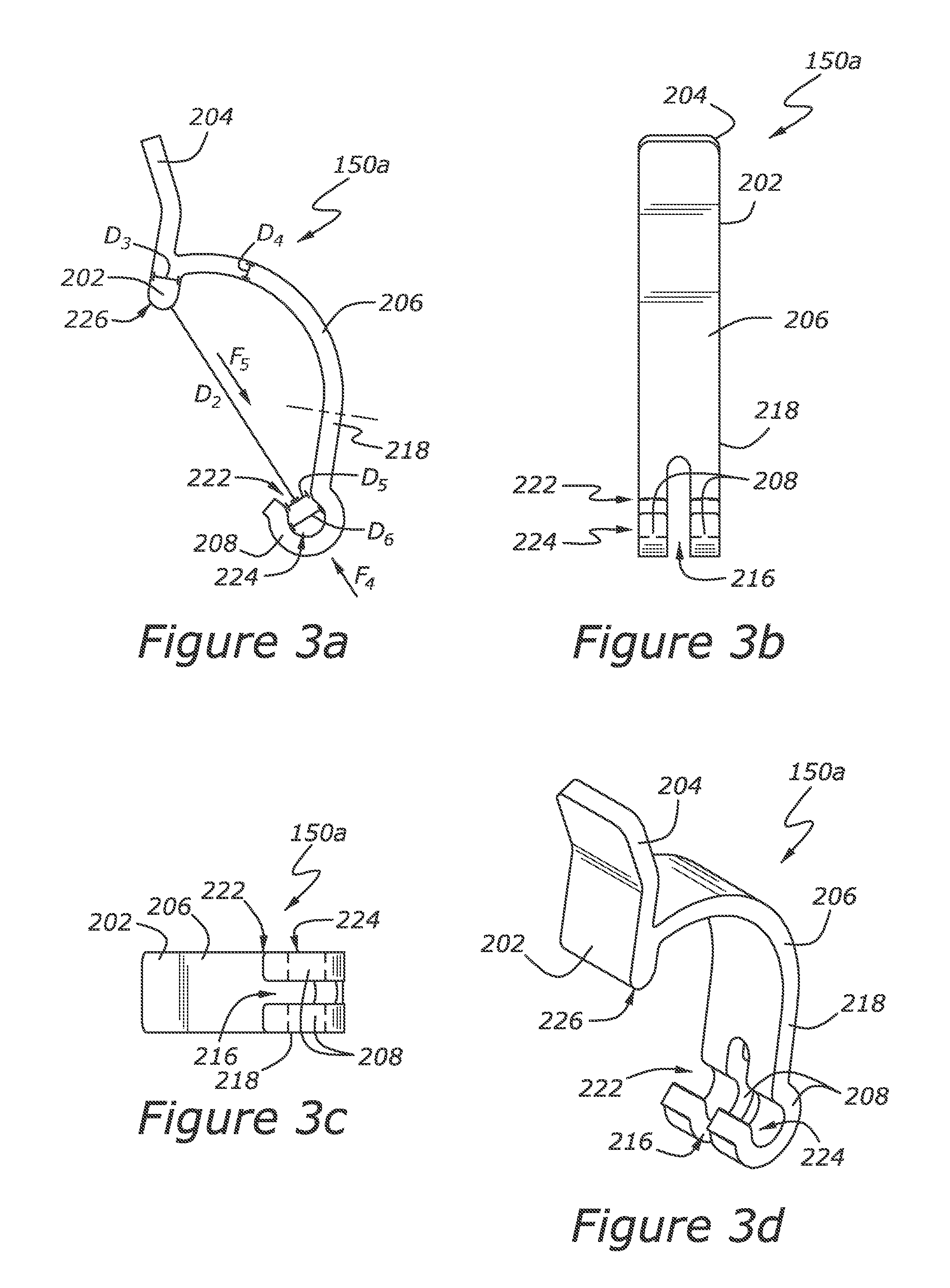
[0007]In this example, elastic deformation of the clamp is distributed over the length of the arm. The spring clamp may also include a hook attachment portion which may be reversibly attached to a rotational axis on the filter casing, allowing a damaged spring clamp to be easily replaced. Additionally, the head piece may include a rounded or chamfered edge and the lever may be located on the head piece. Both of these features may allow the spring clip to move into the engaged position with less applied force. The thickness of the head piece may be greater than the thickness of the arm portion, the attachment portion, and the lever. The greater thickness of the head piece may provide greater material strength in the region of the spring clip which contacts the upper casing and directly applies a downward force on the upper casing in the engaged position.
[0008]In one specific example, a spring clamp is comprised of plastic composite and includes an arc-like arm portion with a first thickness. One end of the spring clamp includes a hook-shaped attachment portion which is reversibly mounted to a rotational axis on a lower casing for a filter. The opposing end of the spring clip includes a head piece with a rounded edge and an upward-projecting lever. The head piece has a second thickness, which is greater than the first thickness. A force may be applied to the lever to slide the rounded edge over a flange on a perimeter of an upper filter casing. As such, the spring clamp may be selectively moved between an engaged position and a disengaged position. In the engaged position, elastic deformation of the spring clamp is distributed over the length of the arc-like arm portion while the head piece contacts the upper filter casing to provide a downward force and the attachment portion provides an upward force on the rotational axis of the lower casing. Combined these features provide a compressive load to the casing and the seal. In this manner, the seal material is compressed and air containing particulate matter will be cleaned as it passes through the filter and into the engine intake. Should the spring clamp undergo damage, the hook may be disengaged from the rotational axis and a new spring clamp may easily installed the damaged spring clamp. Additionally, as the spring clamp is comprised of plastic, it may be colored for easy identification, it may include molded ergonomic features on the lever, and it may be manufactured in a one step procedure. The manufacturing process for plastic composite spring clamps may be advantageous over the multi-step manufacturing procedure required for fabricating metallic spring clamps, which may include post-fabricating steps such as de-burring, heat treating, and corrosion resistant plating.

Problems solved by technology

The compressive load, however, must be limited to prevent over compression of the seal material resulting in seal damage, such as tearing.
Over time, the joint may become permanently deformed or break.
If the compressive load is insufficient, unfiltered air will enter through the seal and particulate matter may enter engine cylinders, causing mechanical wear and oil contamination.
In another example, if the previously described spring clamp is damaged, replacement is difficult as the cylindrical attachment portion of the spring clamp encompasses the rotational axis on the lower casing.
In yet another example, engagement of the spring clamp may be difficult as the head portion has a flat surface and the operational force is exerted a substantially central region of the clamp (the lever being located at the joint).
Should the spring clamp undergo damage, the hook may be disengaged from the rotational axis and a new spring clamp may easily installed the damaged spring clamp.

Method used


Image

  • Spring clamp for an air filter housing
  • Spring clamp for an air filter housing
  • Spring clamp for an air filter housing

Examples


Embodiment Construction

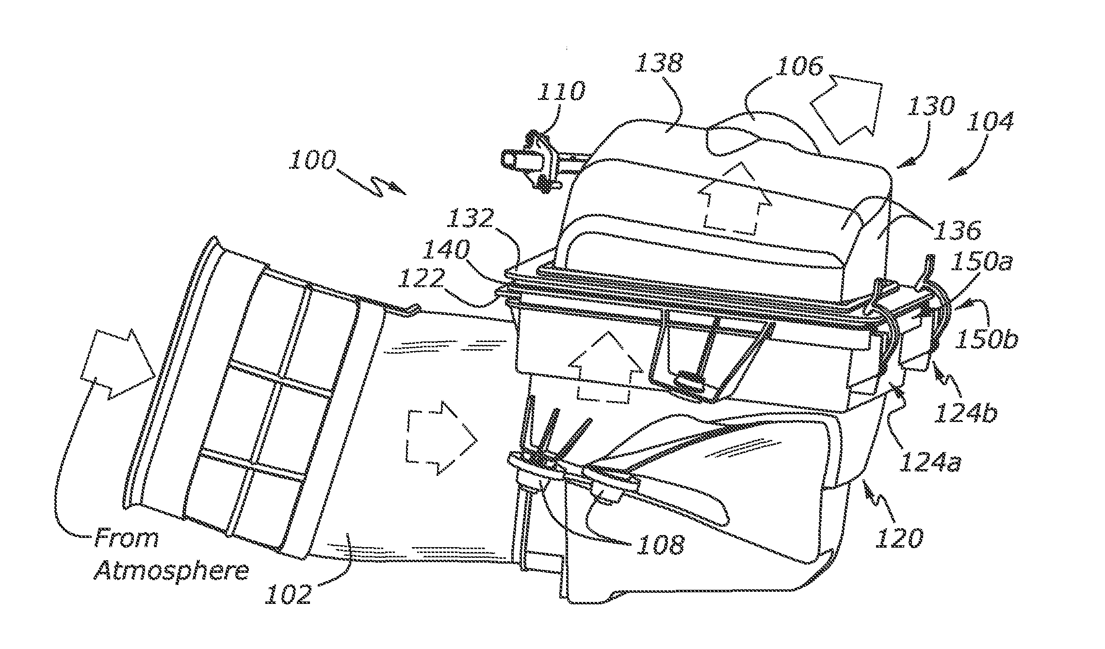
[0014]The following description relates to an air filtration system for a vehicle, such as a passenger vehicle, configured to receive air from the atmosphere, filter particulate matter from the air, and deliver the filtered air to an engine intake. The air filtration system may include an air intake in communication with the atmosphere, a throttle which regulates air flow through the air intake, a filter housing comprising a least two portions (a first portion coupled to the atmospheric air intake and a second portion of filter housing coupled to a filtered air outlet), a filter disposed within the filter housing, a seal substantially encompassing the filter and compressed between the at least two portions of the filter housing, at least one spring clamp to provide a compressive load to the seal, and a filtered air outlet coupling the filter housing to an internal combustion engine. An example embodiment of such an air filtration system is shown in FIG. 1.

[0015]In this embodiment, t...


PUM

PropertyMeasurementUnit
Fractionaaaaaaaaaa
Thicknessaaaaaaaaaa
Forceaaaaaaaaaa

Abstract

A spring clamp for providing a compressive load to a compression seal in an air filtration system for a vehicle. The spring clamp may be comprised of plastic composite and includes an arch-like arm wherein elastic deformation is distributed throughout the arch while providing a compressive load. The spring clamp may include a head piece with a greater thickness than the other parts of the spring clamp to provide greater material strength at a point of contact between the spring clamp and an air filter housing.

Description

FIELD[0001]The present application relates to a spring clamp for providing a compressive load to a compression seal in an air filtration system for a vehicle.BACKGROUND AND SUMMARY[0002]Air filters for vehicles typically comprise an upper casing, a lower casing, a fibrous material, and a compressible seal encompassing the fibrous material. The seal is disposed between the perimeters of the upper and lower casings in a region where the upper and lower casings are mated. The seal requires a continuous compressive load to ensure no gaps develop over time and allow unfiltered air, containing particulate matter, to bypass the filter and continue into the engine intake. The compressive load, however, must be limited to prevent over compression of the seal material resulting in seal damage, such as tearing.[0003]In one approach, described in US Patent Application Publication 2010 / 0043367 A1, compression of a seal between an upper casing and a lower casing is accomplished by a pivotable spr...

Claims


Application Information

Patent Timeline
IPC IPC(8): B01D46/42
CPCB01D46/0002F02M35/10321F02M35/0203B01D2265/028
Inventor KHAMI, ROGERSPEED, LEONROLLINS, SCOTT M.HERMANN, ERIKCHUNG, HA TOLIU, JOHN QINGRUI
Owner FORD GLOBAL TECH LLC
Learn More