
Implantable dialysis access port

a technology of access ports and dialysis, applied in the field of access ports, can solve the problems of affecting the normal life of patients, causing a great burden on patients, and affecting the normal functioning of life, and achieve the effect of preventing the compression of the vessel

Inactive Publication Date: 2006-11-02
CIRCUPORT
View PDF16 Cites 33 Cited by
  • Summary
  • Abstract
  • Description
  • Claims
  • Application Information

AI Technical Summary

Benefits of technology

"The present invention relates to an implantable access port for medical procedures. The invention provides an implantable access port with a hollow port casing having multiple channels for fluid communication. The access port may also include a self-sealing insert to prevent fluid flow through the channels. The invention also provides a method for connecting the access port to a vessel to create a fluid communication pathway. The invention allows for continuous blood flow through the access port and provides a way to filter blood. The invention also provides a port casing core with an aperture for fluid communication and an insert to prevent fluid flow through the aperture. The technical effects of the invention include improved fluid control and filtering capabilities for medical procedures."

Problems solved by technology

Unfortunately, a significant number of individuals suffer from decreased kidney function.
While this procedure may usually be performed at home by the patient it will be appreciated that such a process creates a great burden on the patient, and typically interferes with normal life functioning.
The resulting increased blood through the veins may cause a neo-intimal hyperplasia which could occlude the veins and lead to access loss.
Additionally, the direct flow of blood from an artery into the veins puts undue strain on the local vascular system in general, and the heart in particular.
Finally, because blood is both withdrawn from and returned to the body in the same AV fistula, dialysis is typically inefficient because of the phenomenon of recirculation.
Ports constructed in this manner tend to clot when not in use—especially from the port from which blood is being drawn.
Also, because both catheters are inserted into the same vein, portions of the cleansed blood that has been returned to the body may be recycled back into the dialysis machine, making the procedure inefficient.

Method used


Image

  • Implantable dialysis access port
  • Implantable dialysis access port
  • Implantable dialysis access port

Examples


Embodiment Construction

[0056] In the following is described the embodiments of the implantable dialysis access port of the present invention. In describing the embodiments illustrated in the drawings, specific terminology will be used for the sake of clarity. However, the invention is not intended to be limited to the specific terms so selected, and it is to be understood that each specific term includes all technical equivalents that operate in a similar manner to accomplish a similar purpose.

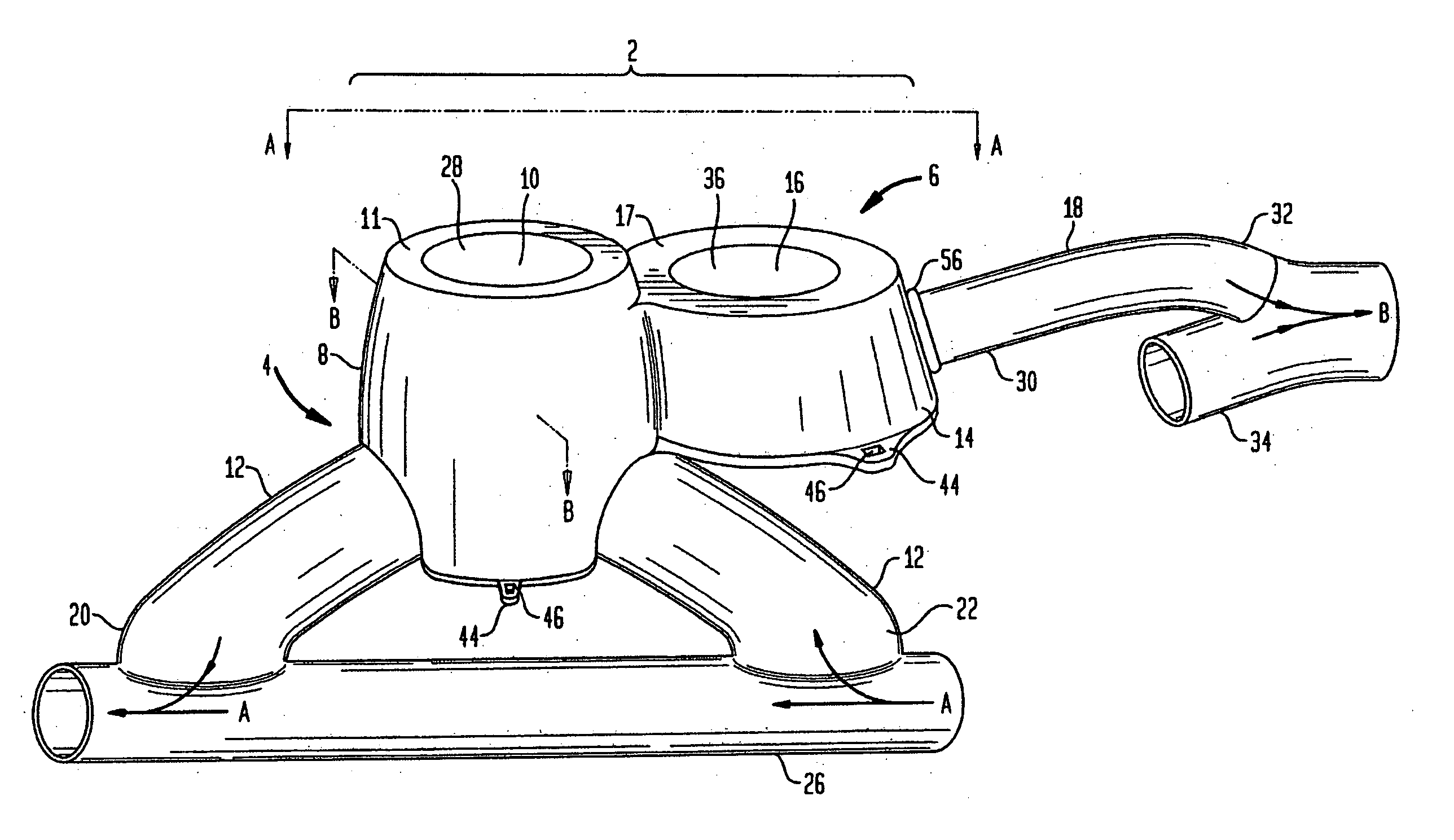
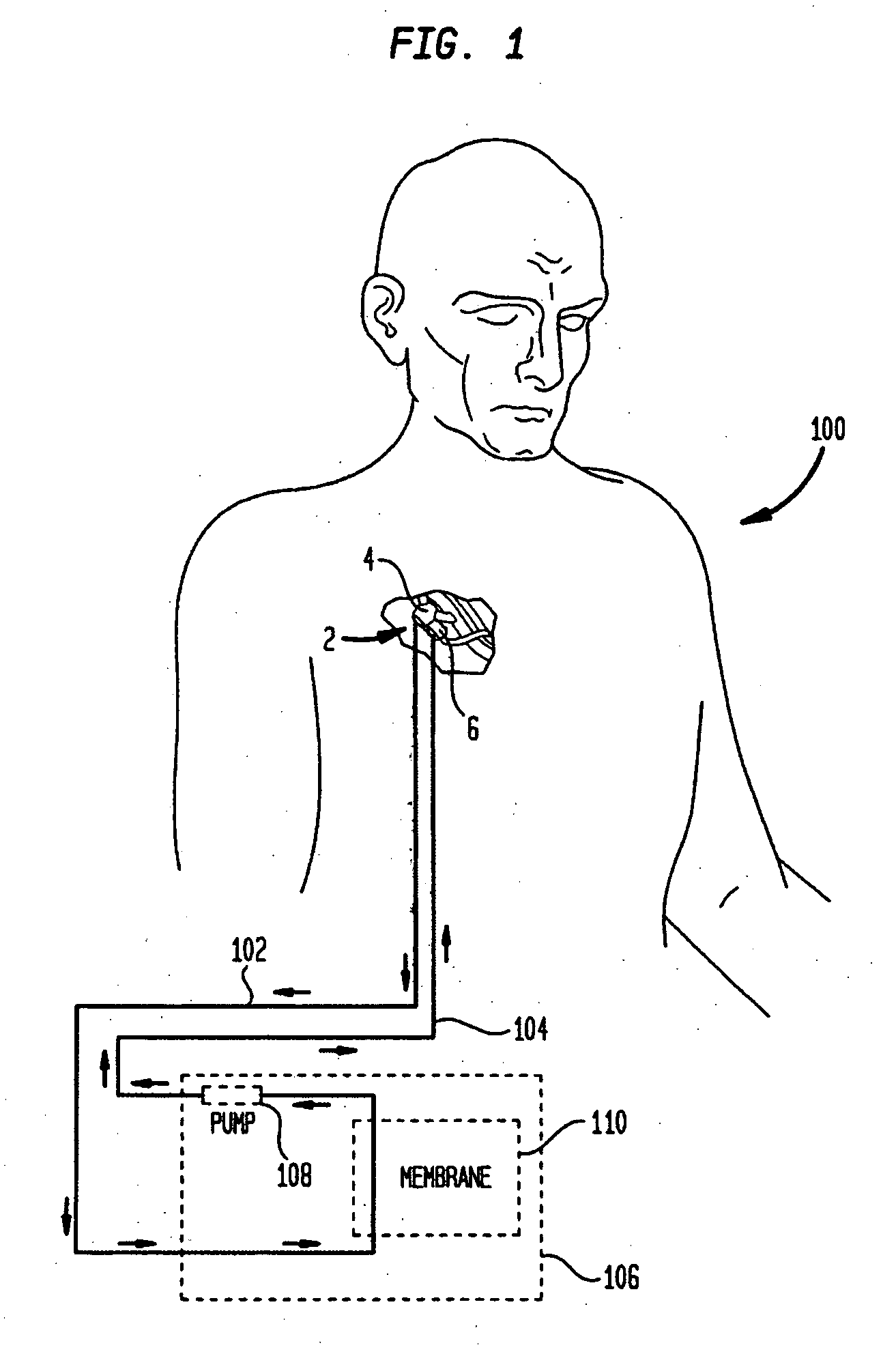
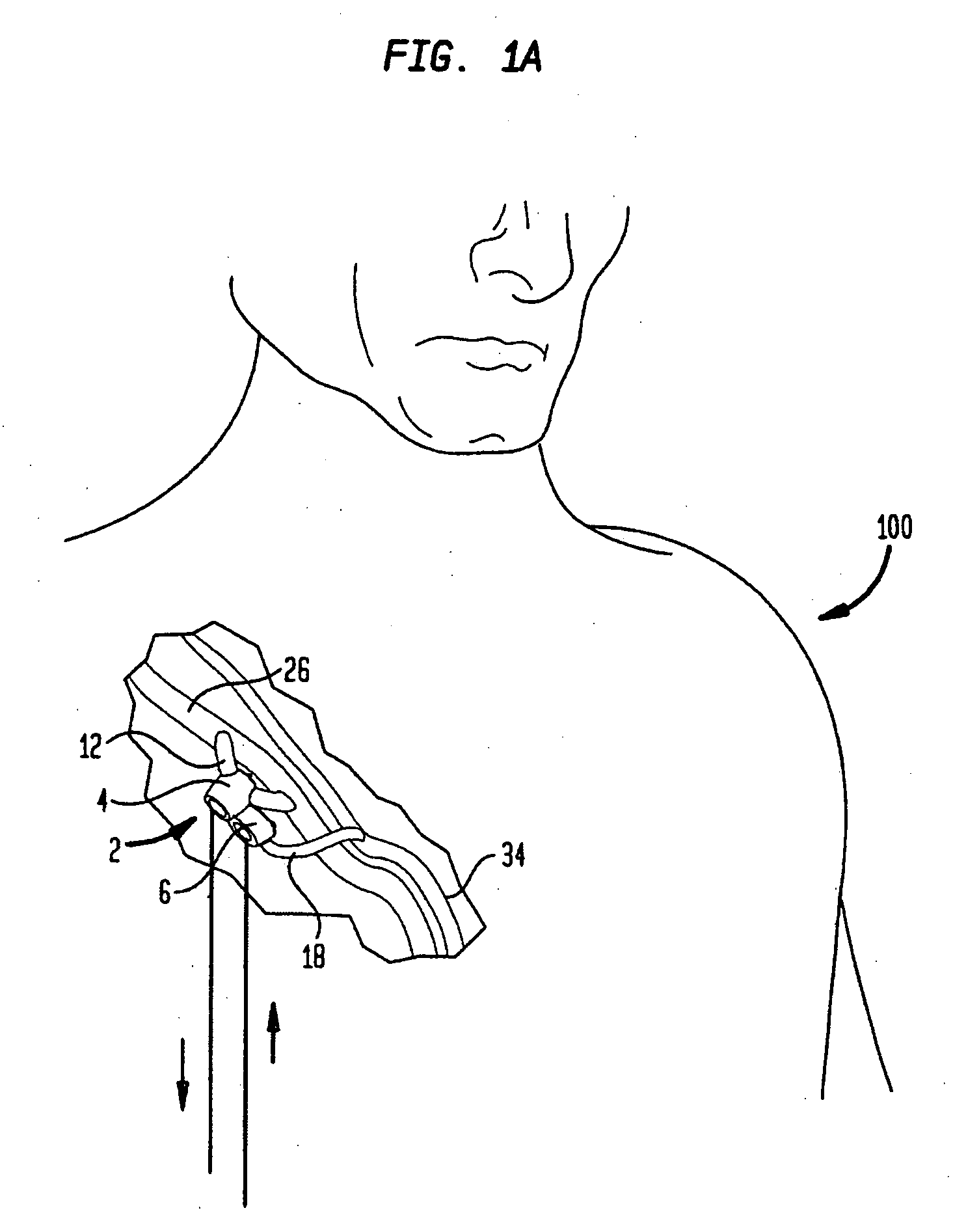
[0057] Referring to the figures, FIG. 1 depicts a diagrammatic view of a typical hemodialysis system utilizing one embodiment of the implantable dialysis access port 2 of the present invention. As shown in FIG. 1, the implantable dialysis port 2 may be implanted into the chest area 100 of the human body. The implantable dialysis port 2 may also be implanted into other areas of the body, so long as it is implanted in reasonable proximity to a medium sized artery, typically between 6 and 8 mm, for use with the implan...


PUM


Abstract

An implantable access post having a port casing core with an aperture therethrough, a patch associated with the port casing core, the patch adapted to be sewn to a vessel to connect the port casing core to the vessel to permit fluid communication from the vessel through the aperture of the port casing core, and an insert disposed within the aperture of the port casing core, the insert adapted to prevent fluid flow through the aperture. The insert may be self-sealing and may include a valve. The port may also include a port outer casing at least partially surrounding the port casing core.

Description

CROSS-REFERENCE TO RELATED APPLICATIONS [0001] This application is a continuation-in-part of U.S. patent application Ser. No. 10 / 682,222 filed Oct. 9, 2003 which claims the benefit of U.S. Provisional Application No. 60 / 417,204 filed Oct. 9, 2002. This application also claims the benefit of U.S. Provisional Application No. 60 / 673,414 filed Apr. 21, 2005. The disclosures of each of the foregoing applications which are hereby incorporated herein by reference.BACKGROUND OF THE INVENTION [0002] The present invention relates to access ports implantable into a mammal to gain access to veins and arteries thereof. Typically, such ports are implanted for use during hemodialysis. The access ports of the present invention may be utilized as an alternative to a typical arteriovenous (hereinafter “AV”) fistula, AV graft, or large central venous catheter used during modern kidney dialysis procedures. These ports are designed to raise the comfort level of a dialysis patient and to reduce the risk ...

Claims


Application Information

Patent Timeline
Patent Type & Authority Applications(United States)
IPC IPC(8): A61K9/22
CPCA61M1/3655A61M2039/0211A61M39/0208
Inventor EDOGA, JOHN K.RICHARD, THIERRY
Owner CIRCUPORT
Learn More