Apparatus and method for automated cutting of the wings from poultry bodies

Active Publication Date: 2012-02-23
NORDISCHER MASCHINENBAU RUD BAADER GMBH CO KG
View PDF0 Cites 1 Cited by
  • Summary
  • Abstract
  • Description
  • Claims
  • Application Information

AI Technical Summary

Benefits of technology

[0010]This object is achieved by an apparatus of the kind mentioned hereinbefore by the fact that the cutting blades of the third pair form a cutting station without a counter-support and each have a cutting edge which is constructed and designed to perform partial cuts leaving the end pieces of the wings on the poultry body, and that the lateral guide rails behind the separating device in the direction of transport T each have a recess to increase the vertical distance between the guide rail and the conveying chain. By dispensing with a counter-support, the product can at least slightly escape the pressure on the product exerted by the cutting blades, so that it is made difficult to cut through completely. The cutting edge of the cutting blades is, by contrast with the state of the art, constructed as a kind of stub edge, so that the length of the cutting edge is shorter than the known cutting blades.
[0011]As a result, in their cutting position the cutting blades leave a portion of the tendons and tissue parts in the region of the joint between the end pieces and the poultry body. In connection with the absence of a counter-support, the design of the cutting 
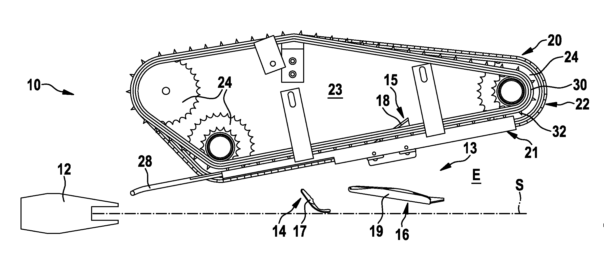
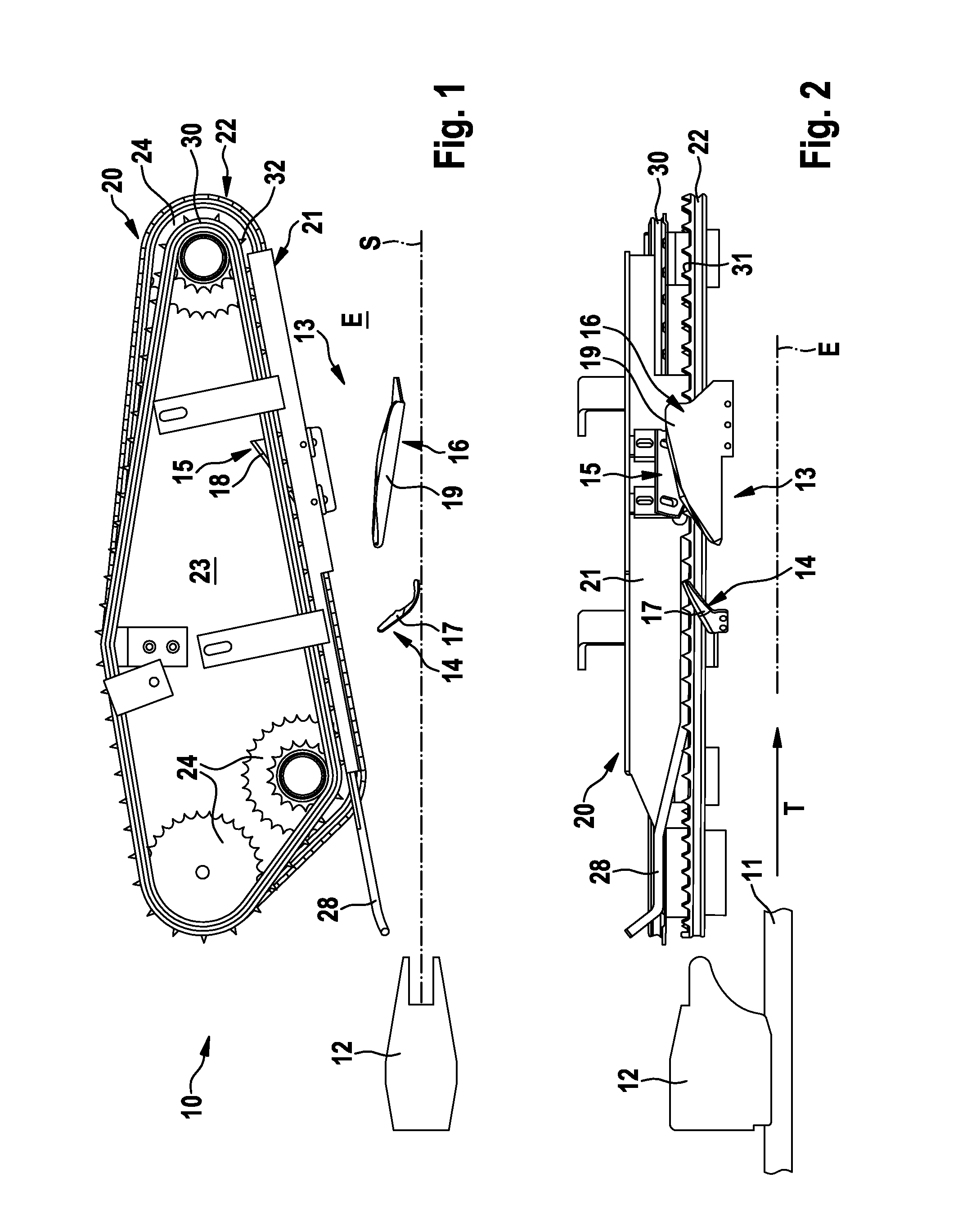
station according to the invention is not able in any position to completely separate the end piece from the poultry body. Due to the recesses in the guide rails and the resulting increase in distance between the guide rails and the conveying chains, clamping of the wings or end pieces is eliminated. To put it another way, a free space for the wings or the end pieces is created by the recess, so that they can be released from the operative connection between the guide rails and the conveying chains and can shoot back to the poultry body due to the abrupt ending of the diverging transport. The further revolving conveying chain is then—due to the absence of an operative connection to the associated guide rail—no longer able to separate or tear the end pieces of the wings from the poultry body. The size of the recess is not geometrically limited in an upward direction, starting from the lower edge, and can also mean that the guide rail ends behind the separating device in the direction of transport T. Due to the combination of features according to the invention, it is possible to perform the premium cut in a completely automated fashion in the case of poultry bodies.
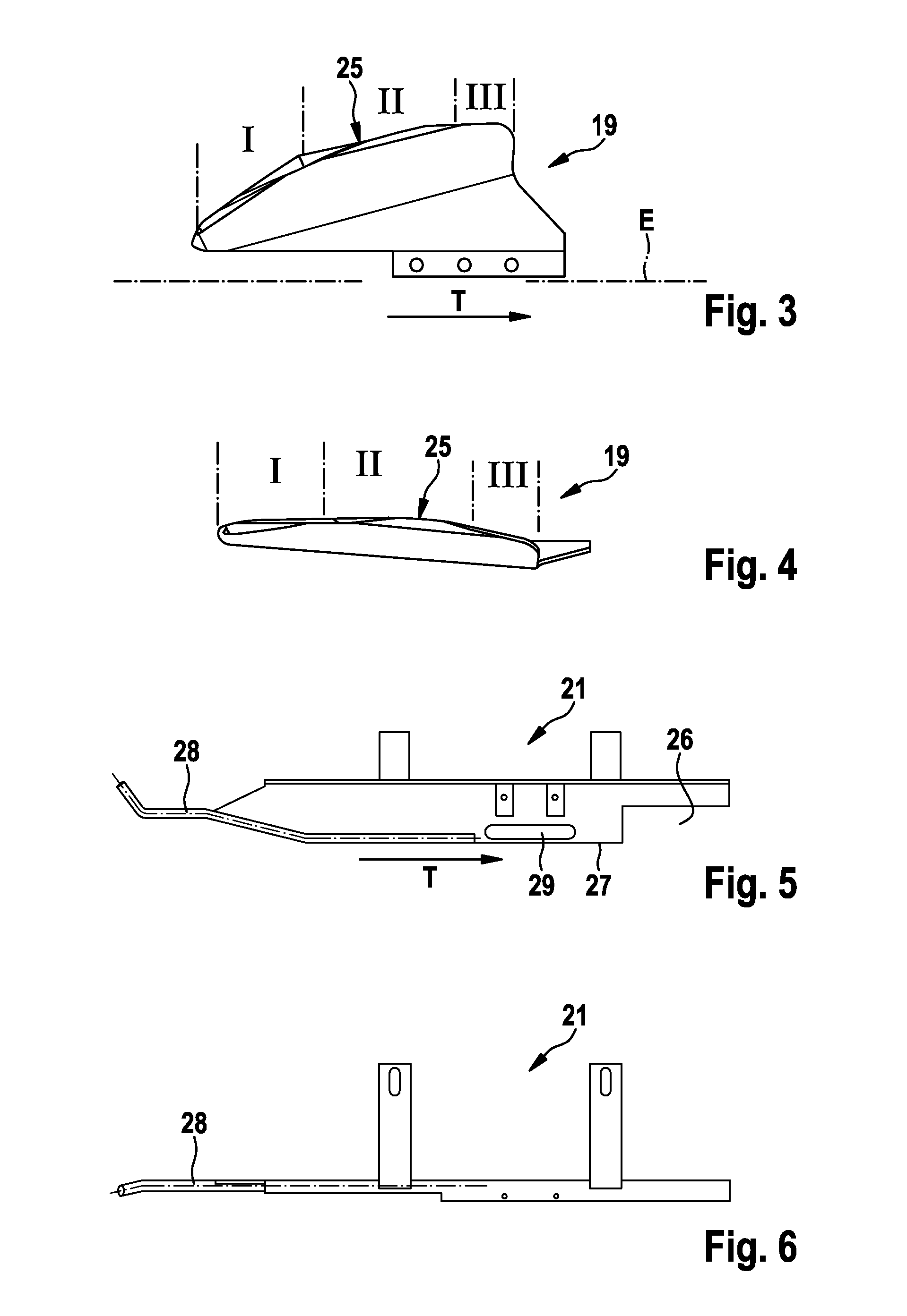
[0012]An appropriate development of the invention as claimed is distinguished in that the cutting blades of the third pair are constructed as approximately triangular delta blades, and the cutting edges facing towards the poultry body have in the direction of transport T a first, blunt section on the input side, a second, sharp-edged section in the middle and a third, blunt section on the output side. Due to the fact that, at least in the end region of the cutting blades, a blunt section is provided, a partial cut which leaves the end piece on the poultry body is assisted. The section formed on the input side, which is also blunt, makes it easier to thread the cutting blades to the preliminary cut performed by the first pair of cutting blades.
[0013]Advantageously, the third section of the cutting edge in the direction of transport T has a lower gradient than the first two sections, referred to the plane of transport E of the poultry bodies. The gradient of the cutting edge extends obliquely upwards in the direction of transport T, starting from the plane of transport E which is defined by the conveying means, so that the poultry bodies run up onto the cutting blades, which are stationary during cutting, in the fashion of a ramp. Due to the fact that the last section of the cutting edge has a lower gradient than the previous sections, which can also be zero (horizontal) or negative (descending), contact of the cutting edges with the poultry body or with the joint between the end pieces and the poultry body can be reduced or completely eliminated, which in turn assists the partial cut that leaves the end piece on the poultry body.

Problems solved by technology

By dispensing with a counter-support, the product can at least slightly escape the pressure on the product exerted by the cutting blades, so that it is made difficult to cut through completely.

Method used


Image

  • Apparatus and method for automated cutting of the wings from poultry bodies
  • Apparatus and method for automated cutting of the wings from poultry bodies
  • Apparatus and method for automated cutting of the wings from poultry bodies

Examples


Embodiment Construction

[0025]The apparatus shown in the drawings is constructed and designed for partially removing the wings from a poultry body. The apparatus 10 shown in FIG. 1 for cutting the wings off poultry bodies is shown only partially, namely only for treating poultry bodies on one side. Symmetrically to the axis of symmetry S is arranged a corresponding part of the apparatus 10 for treating the other side of the poultry body.

[0026]The apparatus 10 comprises a conveying means 11 which is shown schematically only. The conveying means 11 has at least one transport saddle 12 for receiving and holding the poultry bodies. Each transport saddle 12 is usually arranged stationarily but releasably on the conveying means 11, for example, a revolving conveying chain or the like, and movable in rotation with the latter. The poultry bodies to be treated are saddled or fixed on the transport saddle 12 with the breast facing upwards (rear directed towards the transport saddle) and with a neck attachment facing...


PUM


Abstract

An apparatus and method for automated cutting of the wings from poultry bodies are disclosed. The apparatus has transport units that are arranged on each side of the conveying means, each of which includes a guide rail and a conveying chain. The transport units are arranged symmetrically to the conveying means and diverge in the direction of transport T in such a way that the two wings of a poultry body are moved increasingly away from the poultry body during transport along the separating device. The cutting blades of the third pair of separating elements form a cutting station without a counter-support and each has a cutting edge which performs partial cuts leaving the end pieces of the wings on the poultry body. The lateral guide rails behind the separating device each have a recess to increase the vertical distance between the guide rail and the conveying chain.

Description

CROSS-REFERENCE TO RELATED APPLICATIONS[0001]This application claims the benefit of German Patent Application No. 10 2010 035 387.6, filed on Aug. 20, 2010, entitled “APPARATUS AND METHOD FOR AUTOMATED CUTTING OF THE WINGS FROM POULTRY BODIES”, which is incorporated herein by reference.BACKGROUND OF THE INVENTION[0002]Apparatuses and methods for automated cutting of the wings from poultry bodies are often used in the food-processing industry. The bodies of slaughtered poultry such as e.g. chicken, turkey, etc. have the actual poultry body with the wings attached thereto before further treatment and processing. The wings basically have a structure of three components. The so-called end piece is directly attached to the poultry body by a joint. The so-called central piece is arranged on the end piece via a further joint, wherein the so-called tip is arranged on the central piece on the side facing away from the end piece.[0003]Apparatuses and methods are known in which the wings altog...

Claims


Application Information

Patent Timeline
IPC IPC(8): A22C21/00
CPCA22C21/0023
Inventor LANDT, ANDREAS
Owner NORDISCHER MASCHINENBAU RUD BAADER GMBH CO KG
Why Eureka
Try Eureka