
High-voltage apparatus, and radiation source and radioscopic apparatus having the same

Active Publication Date: 2012-02-16
SHIMADZU CORP
View PDF1 Cites 3 Cited by
  • Summary
  • Abstract
  • Description
  • Claims
  • Application Information

AI Technical Summary

Benefits of technology

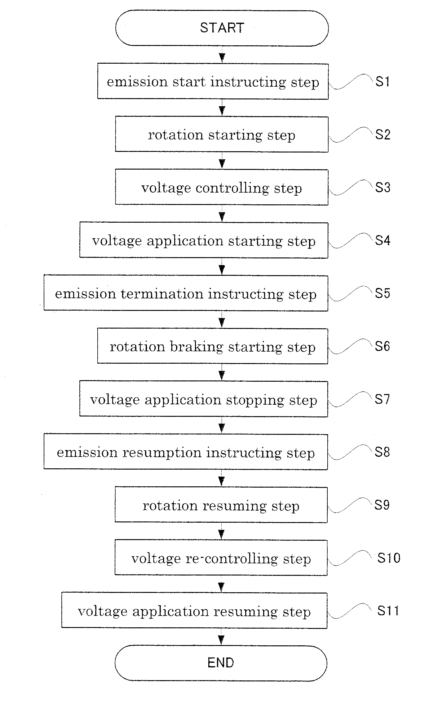
[0017]A high-voltage apparatus according to claim 1 is a high-voltage apparatus for supplying voltage to a radiation source having a rotating anode, a chamber enclosing the rotating anode, a rotating device for rotating the rotating anode, and a rotation control device for controlling the rotating anode, the apparatus comprising a voltage applying device for applying the voltage to the rotating anode; and a voltage application instructing device for instructing the voltage applying device to apply a predetermined voltage for radioscopy from a time when the rotating anode reaches a high number of rotations to an extent of being free from damage.
[0018][Functions and effects] In the high-voltage apparatus according to this invention, a predetermined voltage is applied to the rotating anode after waiting until the number of rotations increases to such an extent that the rotating anode is not damaged. That is, even when fluoroscopy is started in a state of the rotating anode standing still, radiation of an intensity desired by the operator is already outputted from a point of time when the voltage is applied to the rotating anode. Therefore, fluoroscopic images suitable for diagnosis are acquirable immediately after the voltage is applied to the rotating anode. That is, unlike the prior art, there is no need to wait until radiation intensity becomes an intensity suitable for diagnosis after radiation emission is started, and there is no need to irradiate the patient with radiation which cannot be used for diagnosis. Therefore, the patient can be inhibited from being irradiated with unnecessary radiation.
[0025][Functions and effects] The above construction is a specific example of how the voltage application instructing device determines that the number of rotations of the rotating anode has fully increased. Upon lapse of a certain period of time after an end of radiation emission, the rotating anode will be braked to slow down, and the rotating anode will stop completely in several minutes. However, the rotation of the rotating anode will not stop yet for a certain period of time after the braking. When the number of rotations of the rotating anode is maintained high enough, the voltage can be applied between the rotating anode and the cathode immediately without waiting for the delay time from the start of rotation. In the above construction, the number of rotations of the rotating anode is high enough to cause no damage when the time from a point of time a previous application of the voltage to the rotating anode is terminated until a point of time instructions for starting emission of radiation are inputted to the input device is shorter than a predetermined allowed time. In this case, therefore, the voltage application instructing device in the above construction determines that the number of rotations causing no damage to the rotating anode has been reached even before lapse of the delay time from the start of rotation of the rotating anode. This improves the response of the radiation source to an input made by the operator. This allowed time may be varied according to loads applied.
[0031][Functions and effects] According to the above construction, the radioscopic apparatus provided has the radiation source that can output radiation of desired intensity from a start of emission. The patient is not exposed to radiation that cannot be used for diagnosis. Therefore, the radioscopic apparatus provided inhibits exposure to radiation of the patient.

Problems solved by technology

However, at the point of time TA the rotating anode stands still, and it takes some time to reach the predetermined number of rotations RA.

Method used


Image

  • High-voltage apparatus, and radiation source and radioscopic apparatus having the same
  • High-voltage apparatus, and radiation source and radioscopic apparatus having the same
  • High-voltage apparatus, and radiation source and radioscopic apparatus having the same

Examples


embodiment 1

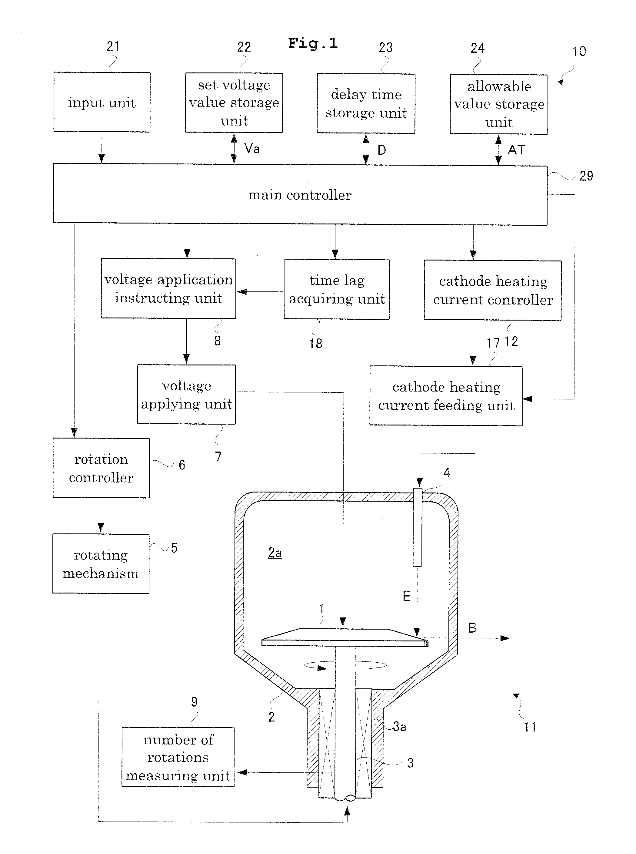
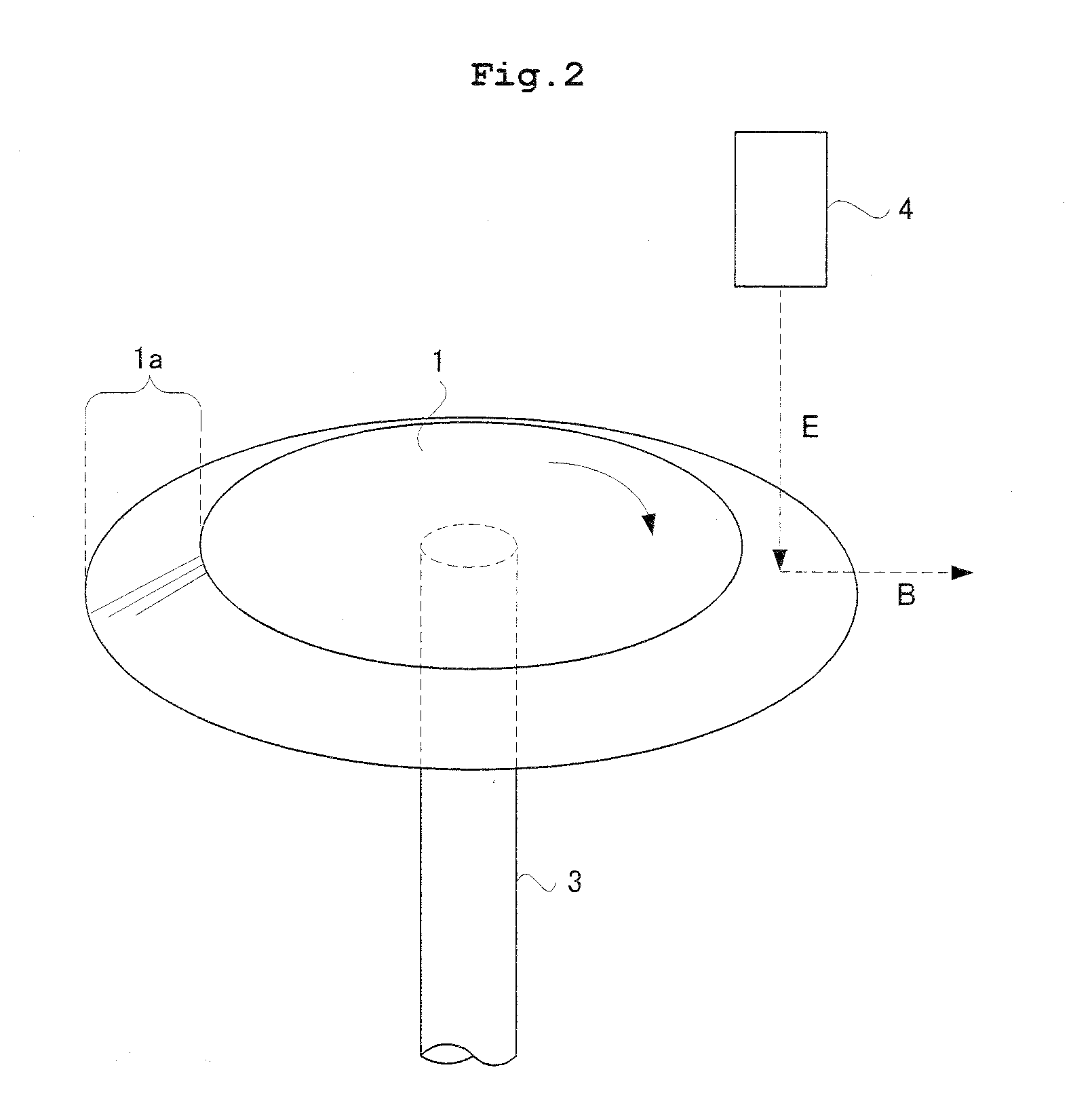
[0053]The construction of an X-ray tube 10 according to this disclosure will be described. The X-ray tube 10 has a rotating anode 1 as shown in FIG. 1. The rotating anode 1 is located in a hollow portion 2a of a vacuum chamber 2 where a vacuum is maintained. FIG. 2 is a perspective view illustrating a construction of a rotating anode according to Embodiment 1. The rotating anode 1 is rotatably supported by a support shaft 3. This rotating anode 1 is disk-shaped, and is tapered to become thinner along directions away from the support shaft 3. That is, the rotating anode 1 is shaped like an umbrella, and has an edge region 1a (see FIG. 2) inclined relative to the support shaft 3. The edge region 1a is also called the target of an electron beam. The vacuum chamber corresponds to the chamber in this disclosure. The X-ray tube corresponds to the radiation source in this disclosure.

[0054]A forward end of a cathode 4 is located in the hollow portion 2a of the vacuum chamber 2, and is oppos...

embodiment 2

[0092]Next, a radioscopic apparatus with the X-ray tube 10 described in Embodiment 1 will be described. The X-rays in the construction of Embodiment 2 are an example of the radiation in this disclosure.

[0093]First, a construction of an X-ray fluoroscopic apparatus 30 according to Embodiment 2 will be described. FIG. 6 is a functional block diagram illustrating the construction of the X-ray apparatus according to Embodiment 2. As shown in FIG. 6, the X-ray fluoroscopic apparatus 30 according to Embodiment 2 includes a top board 32 for supporting a patient M, the X-ray tube 10 disposed above the top board 32 for emitting an X-ray beam in pulse form, a collimator 39 for collimating the X-ray beam emitted from the X-ray tube 10, a flat panel detector (FPD) 34 for detecting X-rays transmitted through the patient M, and an X-ray grid 35 for removing scattered X-rays incident on the FPD 34. The construction in Embodiment 2 includes also a vessel controller 36 for controlling temporal pulse...


PUM


Abstract

In a high-voltage apparatus according to this invention, a predetermined voltage is applied to a rotating anode after waiting until the number of rotations increases to such an extent that the rotating anode is not damaged. That is, X-rays of desired intensity are already outputted from a point of time when the voltage is applied to the rotating anode. Therefore, diagnosis can be performed immediately after the voltage is applied to the rotating anode. That is, unlike the prior art, there is no need to wait until X-ray intensity becomes suitable for diagnosis after X-ray emission is started, and there is no need to irradiate the patient with unnecessary X-rays. Therefore, the patient can be inhibited from being irradiated with excessive X-rays (with an improvement made in a response from when the operator gives instructions for starting fluoroscopy until emission of X-rays suitable for diagnosis).

Description

TECHNICAL FIELD[0001]This invention relates to a high-voltage apparatus for supplying power to a radiation source for which radiation intensity is variable, and a radiation source and a radioscopic apparatus having the same.BACKGROUND ART[0002]A medical institution has a radioscopic apparatus installed therein for acquiring fluoroscopic images of patients. A conventional construction of such a radioscopic apparatus will be described. A conventional radioscopic apparatus includes a top board for supporting a patient, a radiation source disposed above the top board, and a radiation detecting device (FPD) disposed below the top board. The radiation source and FPD are movable along the body axis of the patient M.[0003]The construction of a radiation source 53 will be described specifically. As shown in FIG. 7, the radiation source 53 has a disk-shaped rotating anode 61 with a tapered edge. The rotating anode 61 is located in a hollow portion of a vacuum chamber 62 where a vacuum is main...

Claims


Application Information

Patent Timeline
IPC IPC(8): H05G1/32
CPCH01J35/26H05G1/10H05G1/32H05G1/38H05G1/46
Inventor SAITO, TASUKUFUJII, HIDEKI
Owner SHIMADZU CORP
Learn More