
Method of both cooling and maintaining the uniform temperature of an extended object

a technology of extended objects and uniform temperature, applied in the direction of domestic cooling apparatus, container discharge methods, superconducting magnets/coils, etc., can solve the problems of increasing vapor pressure, using cryostats, and large superconducting coils cannot be cooled using cryocoolers alone, etc., and achieve the effect of rejecting

Inactive Publication Date: 2012-02-16
KWON DANIEL WOOJUNG +2
View PDF0 Cites 2 Cited by
  • Summary
  • Abstract
  • Description
  • Claims
  • Application Information

AI Technical Summary

Benefits of technology

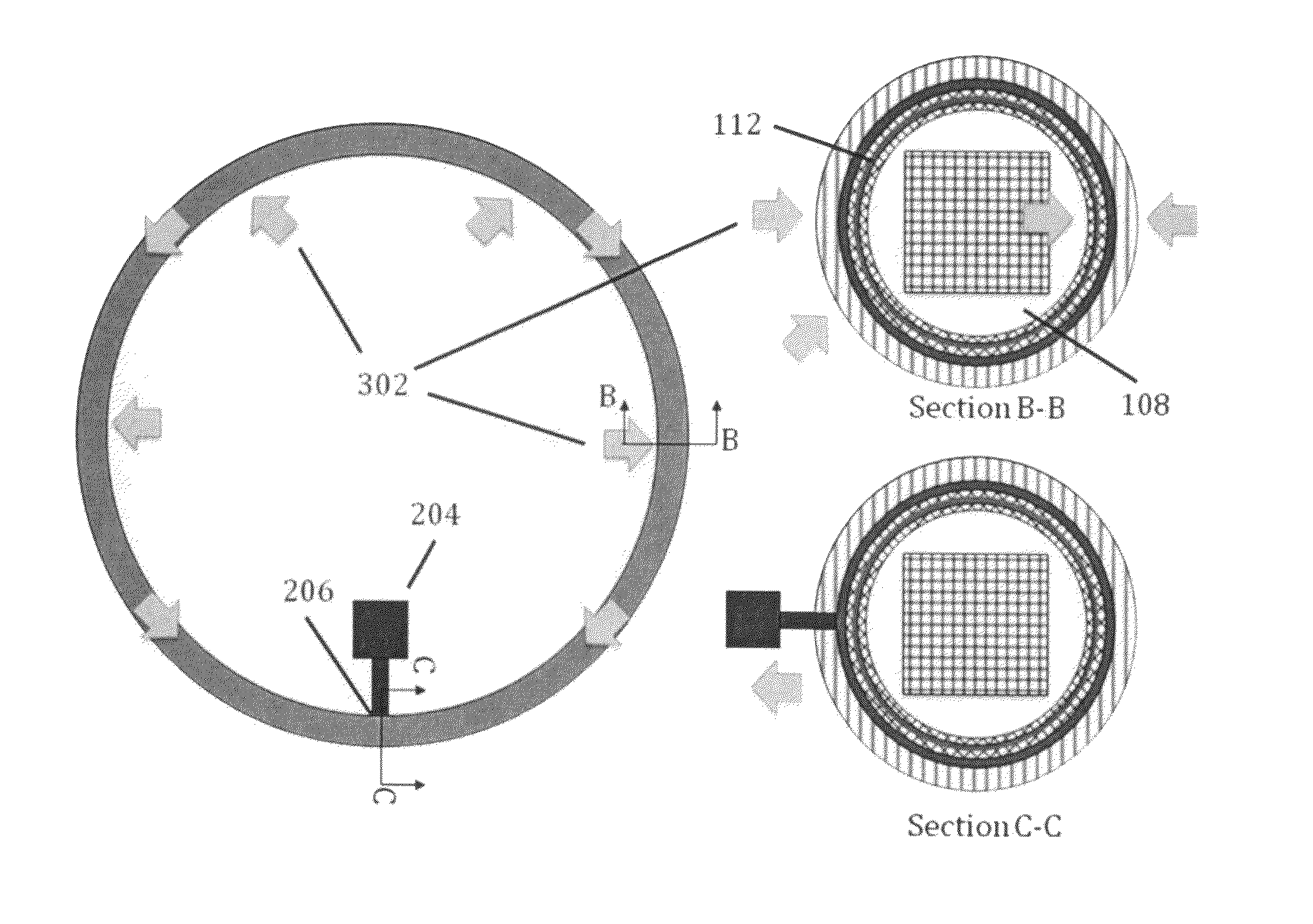
[0028]In accordance with the present invention, an extended structure such as a large superconducting coil is cooled to a uniform cryogenic temperature by embedding it in the vapor space of a heat pipe. The uniform temperature of the structure may be maintained in the presence of spatially and temporally varying external heat sources. The invention uses a much smaller mass and volume of cryogen than a cryostat, and requires only a single point of heat extraction. Unlike a cryostat, an unintentional increase in heat generation by the cooled structure will not cause rapid evaporation of the cryogen, thus offering substantial protection against over-pressuring that could result in loss of cryogen or explosive damage.

Problems solved by technology

These large superconducting coils cannot be cooled using a cryocooler alone, and the use of a cryostat has the disadvantages listed in the last section.
However, quenching with a vapor cooled SCM will not result in an increase in vapor pressure and is therefore a much more easily recoverable fault.
An additional problem with using a cryostat to cool these coils is that the cryogenic liquid between the wires of the coils acts as a dielectric and results in substantial power loss and subsequent boiling of the liquid cryogen.

Method used


Image

  • Method of both cooling and maintaining the uniform temperature of an extended object
  • Method of both cooling and maintaining the uniform temperature of an extended object
  • Method of both cooling and maintaining the uniform temperature of an extended object

Examples


Embodiment Construction

—PREFERRED EMBODIMENT—FIGS.

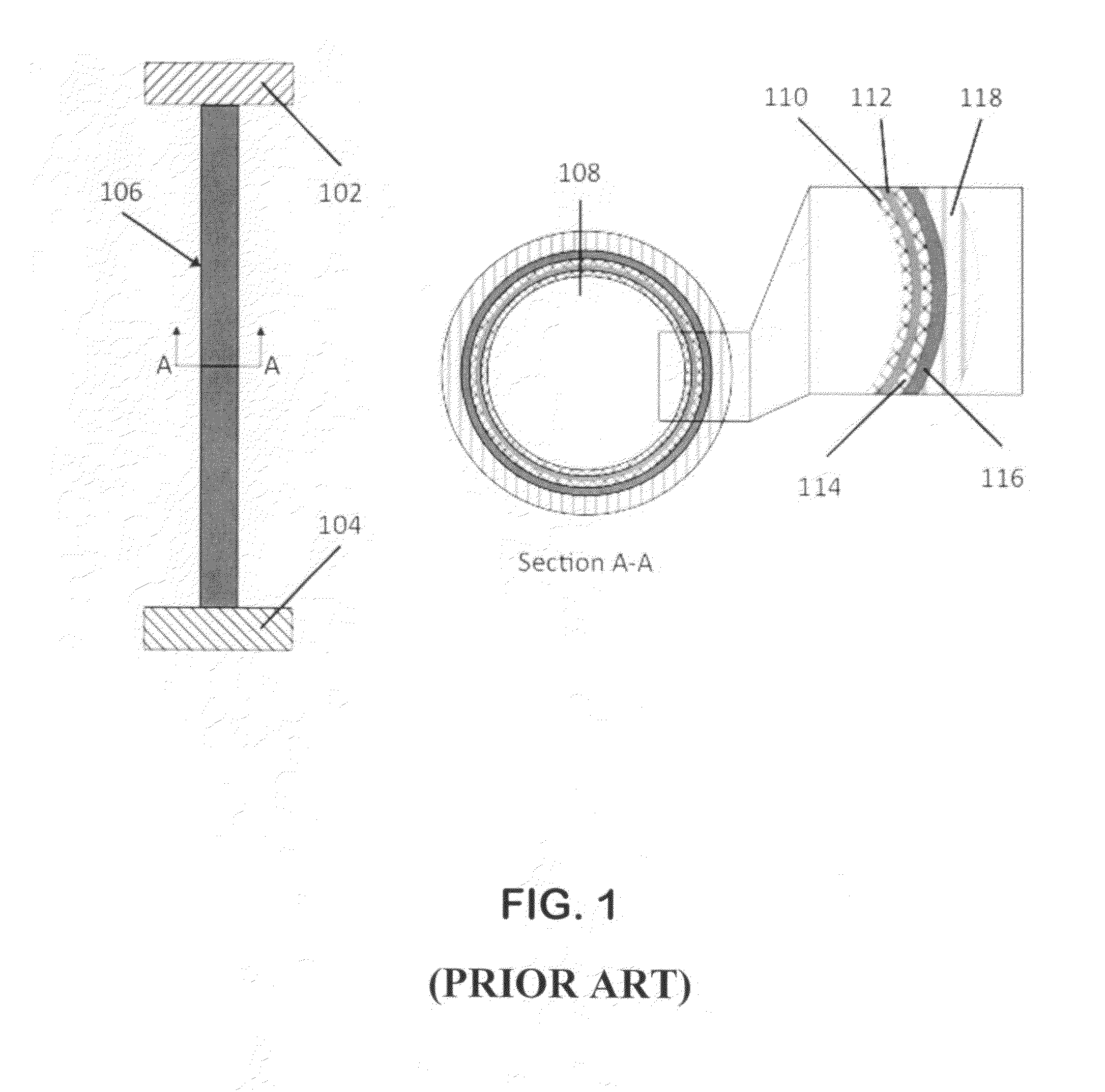
[0031]FIG. 1 shows the prior art of a typical heat pipe assembly 106 conducting heat between an object to be cooled 102 and a cold reservoir 104. A cross-section (A-A) shows one particular embodiment of a typical heat pipe, consisting of an inner vapor space 108 and a number of layers at the wall, shown in the inset. This particular embodiment shows an inner mesh grid 110, a liquid layer of the working fluid 112, an outer mesh grid 114, the wall of the heat pipe 116 and an outer layer of thermal insulation 118.

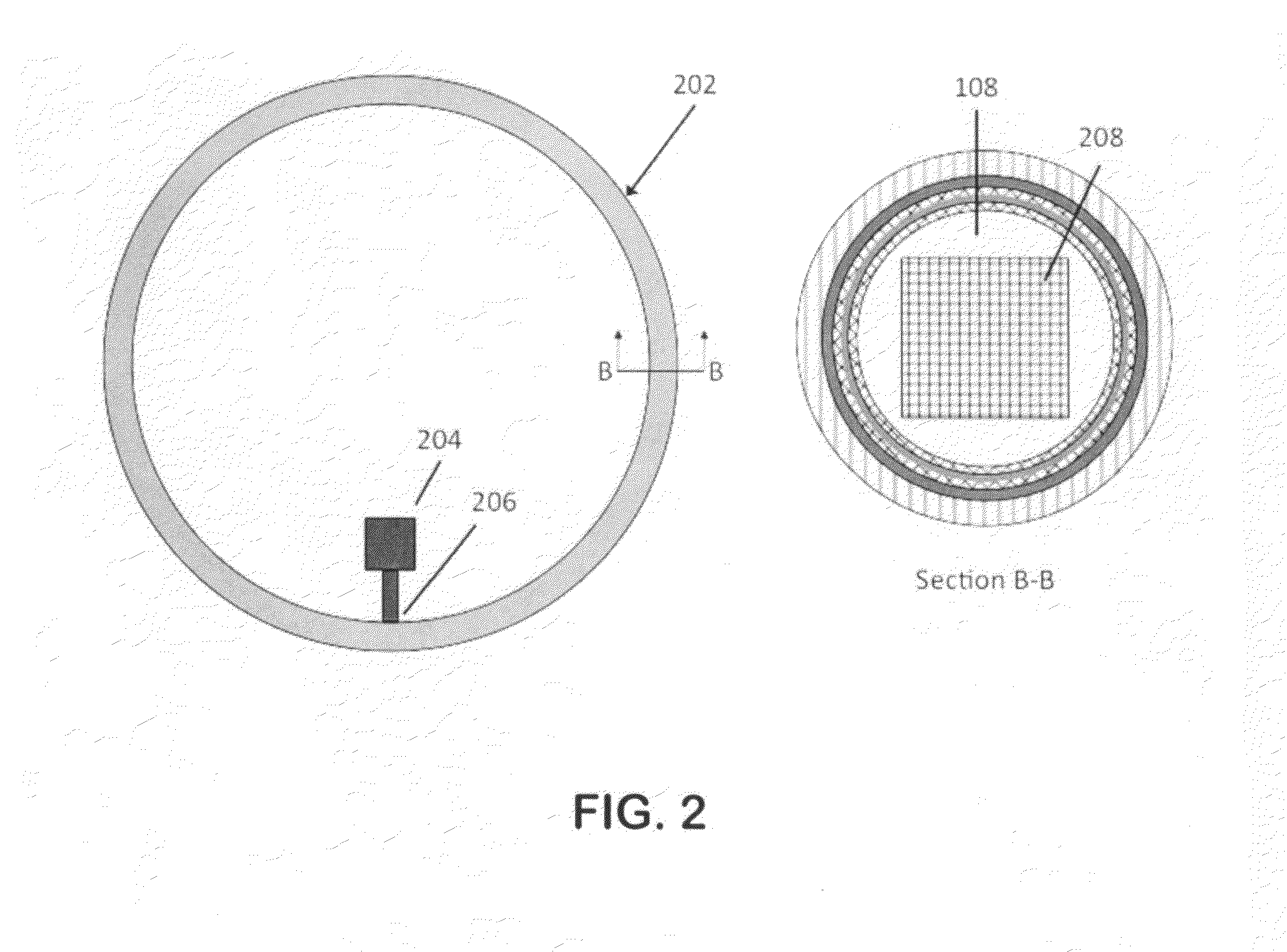
[0032]FIG. 2 shows a preferred embodiment of the current invention, consisting of a closed heat pipe 202 and a cryocooler 204 with its cold tip 206 in contact with the wall of the heat pipe at a single location, which will be the coldest point within the heat pipe. Cross-section B-B shows a similar heat pipe embodiment as in FIG. 1, however the object to be cooled 208 is shown embedded within the vapor space 108 of the heat pipe. The wall layers are ...


PUM


Abstract

A general method of cooling and maintaining the uniform temperature of an extended structure is provided with specific application discussed of keeping a superconducting coil at cryogenic temperatures in the presence of external heat loads that may be variable in space and time. The approach embeds the structure to be cooled (208) into the vapor space (108) of a heat pipe assembly (202), which consists of an outer wall (116), a fluid wicking mechanism (110, 114), thermal insulation (118) and a mechanism for heat extraction, such as the cold tip (206) of a cryocooler (204).

Description

CROSS-REFERENCE TO RELATED APPLICATIONS [0001]Not ApplicableFEDERALLY SPONSORED RESEARCH [0002]Not ApplicableSEQUENCE LISTING OR PROGRAM [0003]Not ApplicableBACKGROUND OF THE INVENTION [0004]1. Field of the Invention[0005]This invention pertains to the cryogenic thermal control of large structures, with a specific example being to uniformly maintain coils of superconducting wire at cryogenic temperatures.[0006]2. Prior and Related Art[0007]Superconducting materials (SCMs) are finding ever-increasing applications in a variety of technology areas. However, at the present time their use depends on the ability to maintain them at cryogenic temperatures, since they need refrigeration to overcome two sources of heat loading. The first is any heat leaking into the system from the surrounding environment. The second is any internal heat generation in the device.[0008]For small volumes or surfaces, their temperatures can be maintained using cryocoolers by connecting the cold tip of the cryoc...

Claims


Application Information

Patent Timeline
Patent Type & Authority Applications(United States)
IPC IPC(8): F25B19/00F28D15/00F17C13/00
CPCF28D15/04F28D2021/0077F25D19/006H01F6/04
Inventor KWON, DANIEL WOOJUNGSEDWICK, RAYMOND J.MILLER, DAVID W.
Owner KWON DANIEL WOOJUNG
Learn More