Determining position and orientation of a dental implant

Inactive Publication Date: 2012-02-09
STRAUMANN HLDG AG
View PDF8 Cites 21 Cited by
  • Summary
  • Abstract
  • Description
  • Claims
  • Application Information

AI Technical Summary

Benefits of technology

[0005]Therefore, a problem to be solved by the present invention is to determine the position and orientation of a dental implant with a high precision. At the same time, it is desirable that the scanning procedure is relatively simple, especially in case the scanning is performed directly in a patient's mouth where a long-lasting scanning procedure should be avoided.
[0018]In a further embodiment of the present invention, the scan geometry of the scan body is such that some parts of the scan geometry are light reflective and / or some parts of the scan geometry are non-light reflective, for instance, only a part of a plane area is light reflective and the rest of the plane area is non-light reflective (e.g. the inner part of a plane are is light reflective whereas the border area of a plane area is non-light reflective). In this way, it is possible to simplify the recognition of plane areas during the scanning / reconstruction procedure. Alternatively, it maybe sufficient to have different regions with different reflection coefficients in order to allow an easy detection of the plane areas.

Problems solved by technology

Whereas there is usually plenty of space for placing a dental implant between two neighboring teeth, for instance, the situation is more tricky for the corresponding dental prosthesis.
Whereas dental implants and scan bodies can be produced with high precision, the above-mentioned scanning procedure can be less precise, particularly in situations where distinctive parts, such as corners or edges, of a scan body are only partly visible.

Method used


Image

  • Determining position and orientation of a dental implant
  • Determining position and orientation of a dental implant
  • Determining position and orientation of a dental implant

Examples


Embodiment Construction

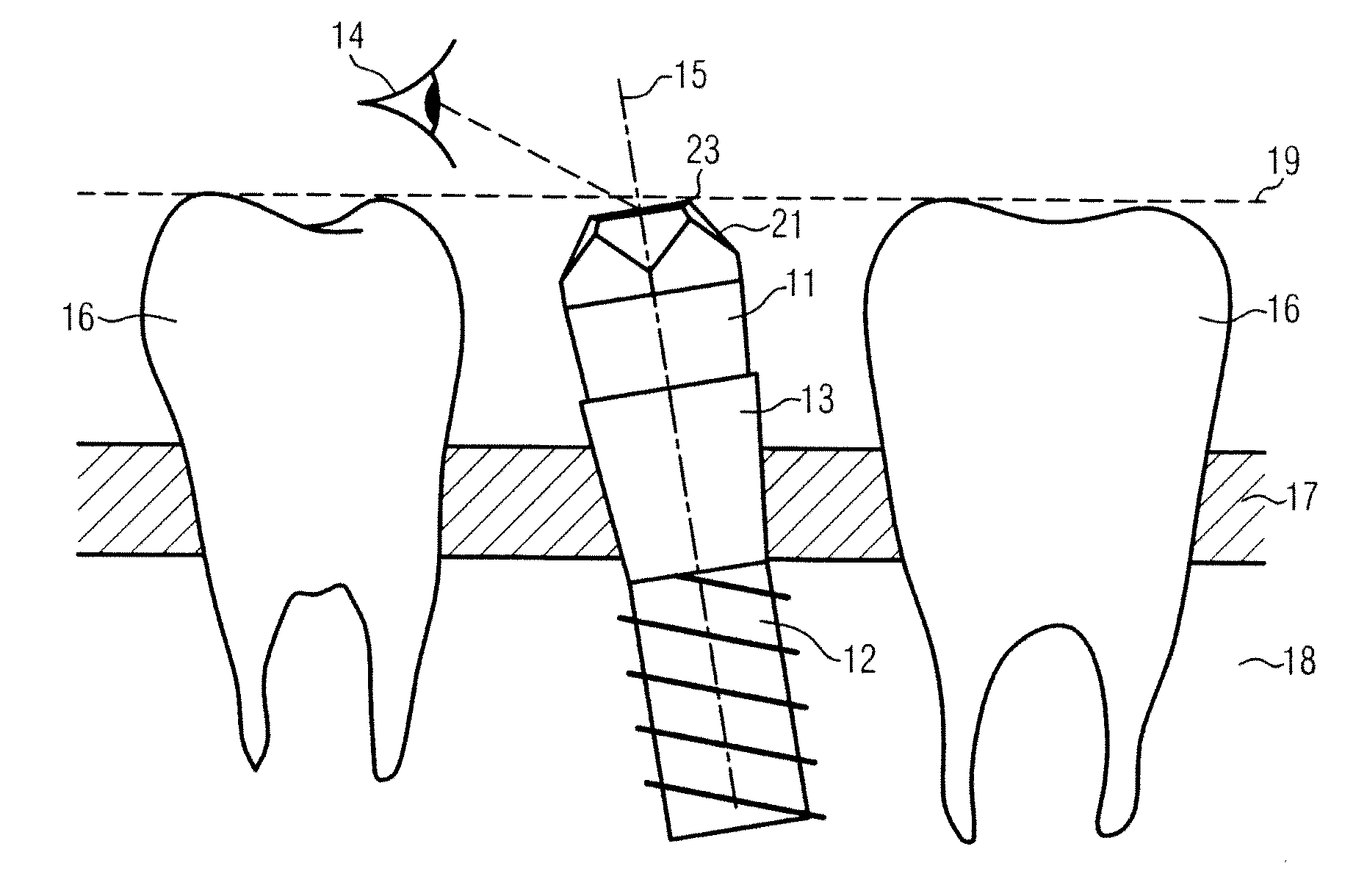
[0024]In FIG. 1, a possible set-up for determining a position and an orientation of an dental implant 12 is illustrated. The set-up either reflects the situation in the mouth of a patient or reflects the situation in a model of a patient's mouth. An implant 12 is fixed in the bone 18 of a jaw. Above the bone 18 there is layer of gingiva 17. A scan body 11 is attached to the implant 12 via an adaptor piece 13 which is located partly above the level of the gingival 17. To the left and to the right of the scan body 11, two neighbouring teeth 16 are illustrated. However, in some cases, there is only one neighbouring tooth 16 next to the implant 12. It should be noted that the longitudinal axis 15 of the scan body 11 and / or the implant 12 and / or the adaptor piece 13 is not necessarily exactly vertical or is not exactly perpendicular to the surface of the bone 18, respectively. Further, when scanning the scan geometry 21 of the scan body 11, the point of view 14 of the scanning device is ...


PUM


Abstract

Method for determining a position and an orientation of a dental implant includes scanning a surface of a scan body connected to the implant wherein a plurality of data points is determined which correspond to positions of points that are located on the surface of the scan body. The method further included reconstructing at least three planes based on the data points, reconstructing intersection information of the reconstructed planes, where the intersection information includes the reconstruction of straight intersection lines and of intersection points, and determining the position and the orientation of the implant based on the reconstructed intersection information.

Description

FIELD OF THE INVENTION[0001]The invention concerns a method, which can be executed by a computing device and / or can be stored in the form of computer executable instructions on a computer-readable medium, for determining a position and an orientation of a dental implant. Further, the invention concerns a scan body for determining a position and an orientation of a dental implant.BACKGROUND[0002]In the field of artificial tooth replacements where one tooth or even several teeth have to be replaced, the corresponding dental prosthesis are usually fixed in a patient's mouth via a dental implant which is fixed (e.g. like a screw) in the bone of a patient's jaw. Whereas there is usually plenty of space for placing a dental implant between two neighboring teeth, for instance, the situation is more tricky for the corresponding dental prosthesis. In order to achieve a qualitatively and aesthetically good result, a dental prosthesis has to fit almost perfectly between neighboring teeth on on...

Claims


Application Information

Patent Timeline
IPC IPC(8): G06F15/00G06F17/50
CPCA61C8/0001A61C13/34A61C13/0004A61C9/0053A61C13/1016A61C8/00A61C13/00
Inventor LAWITSCHKA, UWEHOMANN, FRANKSTRAUB, BENJAMIN
Owner STRAUMANN HLDG AG
Why Eureka
Try Eureka