
Method and Receiver For Jointly Decoding Received Communication Signals Using Maximum Likelihood Detection

a communication signal and maximum likelihood detection technology, applied in the field of receivers and methods for jointly decoding received communication signals, can solve the problems of complex methods used for combating interference, limiting performance, and reducing the efficiency of the receiver, so as to achieve the effect of designing a rather complex and consequently expensive receiver

Active Publication Date: 2012-02-09
TELEFON AB LM ERICSSON (PUBL)
View PDF1 Cites 16 Cited by
  • Summary
  • Abstract
  • Description
  • Claims
  • Application Information

AI Technical Summary

Benefits of technology

[0007]It is a general object of the invention to provide a method and receiver for decoding received communication signals having a balanced trade-off between the complexity of the receiver and the performance.
[0009]It is another object of the present invention to provide a method and receiver for decoding a received communication signal wherein an equalized and frequency flat channel is provided, and wherein also spatially coloured noise is suppressed.

Problems solved by technology

However, such a scheme would in most cases lead to unwanted noise amplification limiting the performance.
The complexity of the methods used for combating the interference competes with a desire to cancel the interference to as large extent as possible.
The designer thus stands before the choice of using interference combating algorithms having less than optimal performance and designing a rather complex and consequently expensive receiver.
In short, there is a trade-off between complexity of receiver and performance in terms of accuracy.
An advanced detection scheme is the maximum likelihood detection (MLD), but it has a computational complexity that is exponential with the number of modulation symbols.

Method used


Image

  • Method and Receiver For Jointly Decoding Received Communication Signals Using Maximum Likelihood Detection
  • Method and Receiver For Jointly Decoding Received Communication Signals Using Maximum Likelihood Detection
  • Method and Receiver For Jointly Decoding Received Communication Signals Using Maximum Likelihood Detection

Examples


Embodiment Construction

[0036]Only parts of a telecommunication system necessary for the understanding of the present invention are described. For clarity, descriptions of well-known devices are thus omitted.

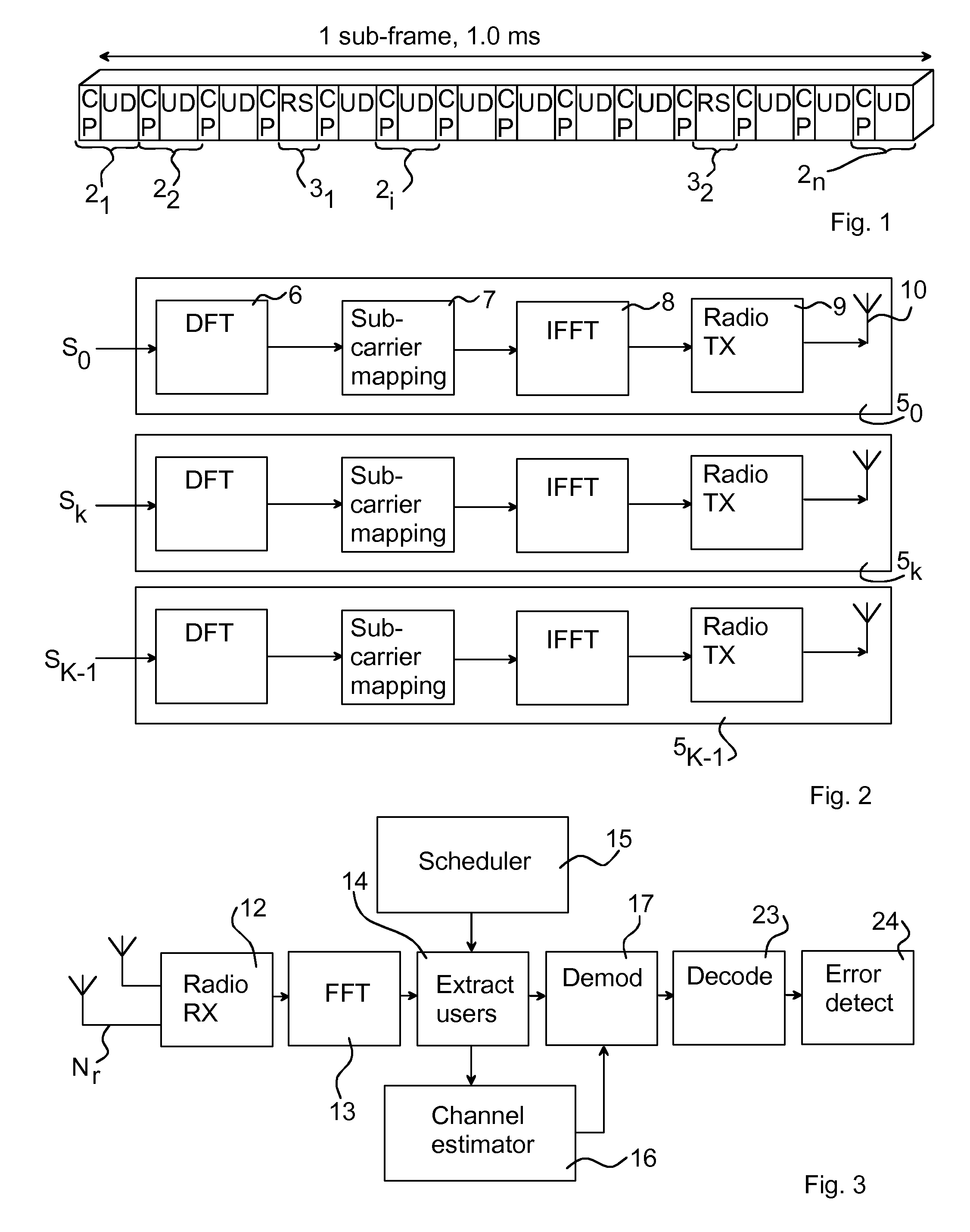
[0037]As mentioned in the introductory part, the uplink for LTE is based on SC-FDMA, sometimes also denoted DFTS-OFDM (Discrete Fourier Transform Spread-OFDM) since SC-FDMA can be regarded as a DFT spread OFDM. FIG. 1 illustrates one sub-frame 1 for uplink LTE. In the LTE uplink, several SC-FDMA symbols 21, . . . , 2i, . . . , 2n form the sub-frame 1. In particular, the sub-frame comprises 12 SC-FDMA symbols 21, . . . , 2i, . . . , 2n with user data (UD) and a respective cyclic prefix (CP), n in the illustrated case being equal to 12. The sub-frame 1 further comprises two symbols 31, 32 with reference signals (RS), for enabling the establishment of channel parameters, the reference signals sometimes also denoted pilot signals or training signals. The present invention is mainly concerned with such SC-F...


PUM


Abstract

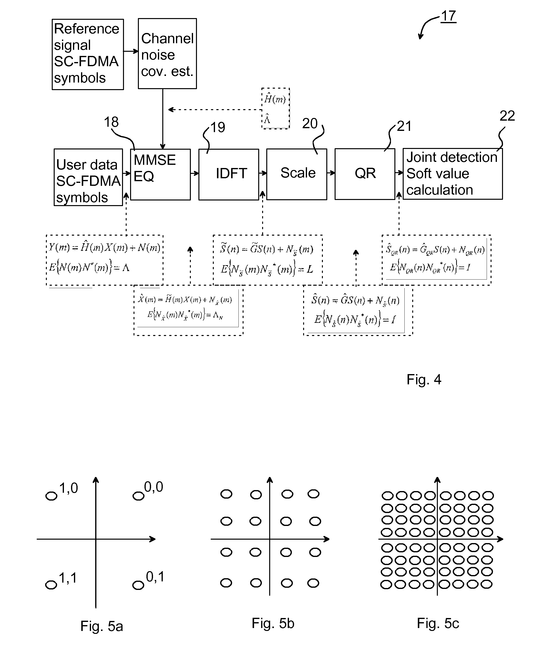
The present invention relates to a method in a receiver for decoding at least two received communication signals, wherein the communication signals are modulated, pre-coded by a discrete Fourier transform and transmitted by means of single-carrier frequency division multiple access scheme (SC-FDMA). The method comprises the steps of: performing an antenna combining and equalization on a signal observed at the receiver; performing inverse discrete Fourier transform on a model of the observed signal; whitening a time domain model of the observed signal; and jointly detecting the received at least two communication signals by performing soft value calculations based on maximum likelihood detection of a whitened time domain model using a whitened time domain channel estimate.

Description

TECHNICAL FIELD OF THE INVENTION[0001]The present invention relates generally to the field of wireless telecommunications and, in particular, to methods and means for decoding received communication signals.BACKGROUND OF THE INVENTION[0002]LTE (Long-term evolution) is a project within the 3GPP (3rd Generation Partnership Project) with an aim to improve the UMTS (Universal Mobile Telecommunications System) mobile phone standard for coping with future technology evolutions. The LTE comprises developing a new air interface standard, and the downlink (base station to user equipment) will be based on OFDMA (orthogonal frequency division multiple access). For the uplink (user equipment to base station), SC-FDMA (single carrier frequency division multiple access) is an attractive choice as SC-FDMA has a lower peak-to-average power ratio than OFDM. The lower peak-to-average power ratio entails improved transmitter power efficiency for the battery-operated user equipment, which is an importa...

Claims


Application Information

Patent Timeline
Patent Type & Authority Applications(United States)
IPC IPC(8): H04J1/00
CPCH04L25/0204H04L25/0246H04L25/025H04L25/03159H04L25/03216H04L2025/03375H04L25/0328H04L25/03299H04L25/03305H04L25/03318H04L27/2647H04L25/03254
Inventor SAHLIN, HENRIKLINDGREN, ULFNAUCLER, PETERPARK, CHESTER
Owner TELEFON AB LM ERICSSON (PUBL)
Learn More