Iron-core coil assembly

a technology of iron-core coils and assembly parts, which is applied in the direction of basic electric elements, inductance with magnetic cores, electrical apparatus, etc., can solve the problems of limited diameter of enameled wires used by traditional winding machines, wires (enameled wires) and increase the difficulty of winding wires onto the surface of closed iron-core devices. , to achieve the effect of further minimization

Inactive Publication Date: 2012-02-02
ADVANCED CONNECTION TECH
View PDF3 Cites 7 Cited by
  • Summary
  • Abstract
  • Description
  • Claims
  • Application Information

AI Technical Summary

Benefits of technology

[0011]Since use of a winding machine is no longer necessary, the size of the iron-core coil assembly is not limited by a winding machine, and thus can be miniaturized further.

Problems solved by technology

However, the difficulty involved in winding wire onto the surface of the closed iron-core device is also increased greatly.
Furthermore, the enameled wires used by the traditional winding machine dedicated to wind a wire (enameled wire), onto the surface of an iron-core device are limited by diameter, since slender enameled wire which is too thin can easily break during the winding process.
Where the diameter of the enameled wire cannot be reduced any further, the size of the iron-core coil assembly is accordingly limited, and further miniaturization becomes difficult.
However, using such a method the enameled wire must also be wound circle by circle on the winding area of the iron-core device manually or with the aid of a machine, which not only prolongs the preparation process unnecessarily, but also leads to a lowered inductance value of the whole iron-core coil assembly due to non-uniform surfaces (junction), formed by joining the iron cores.

Method used


Image

  • Iron-core coil assembly
  • Iron-core coil assembly
  • Iron-core coil assembly

Examples


Embodiment Construction

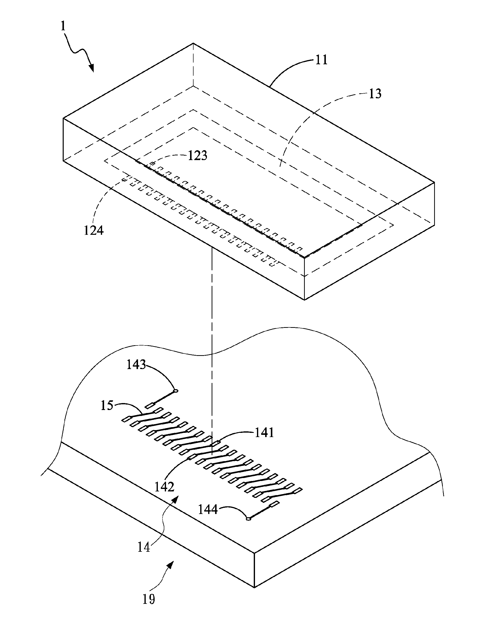
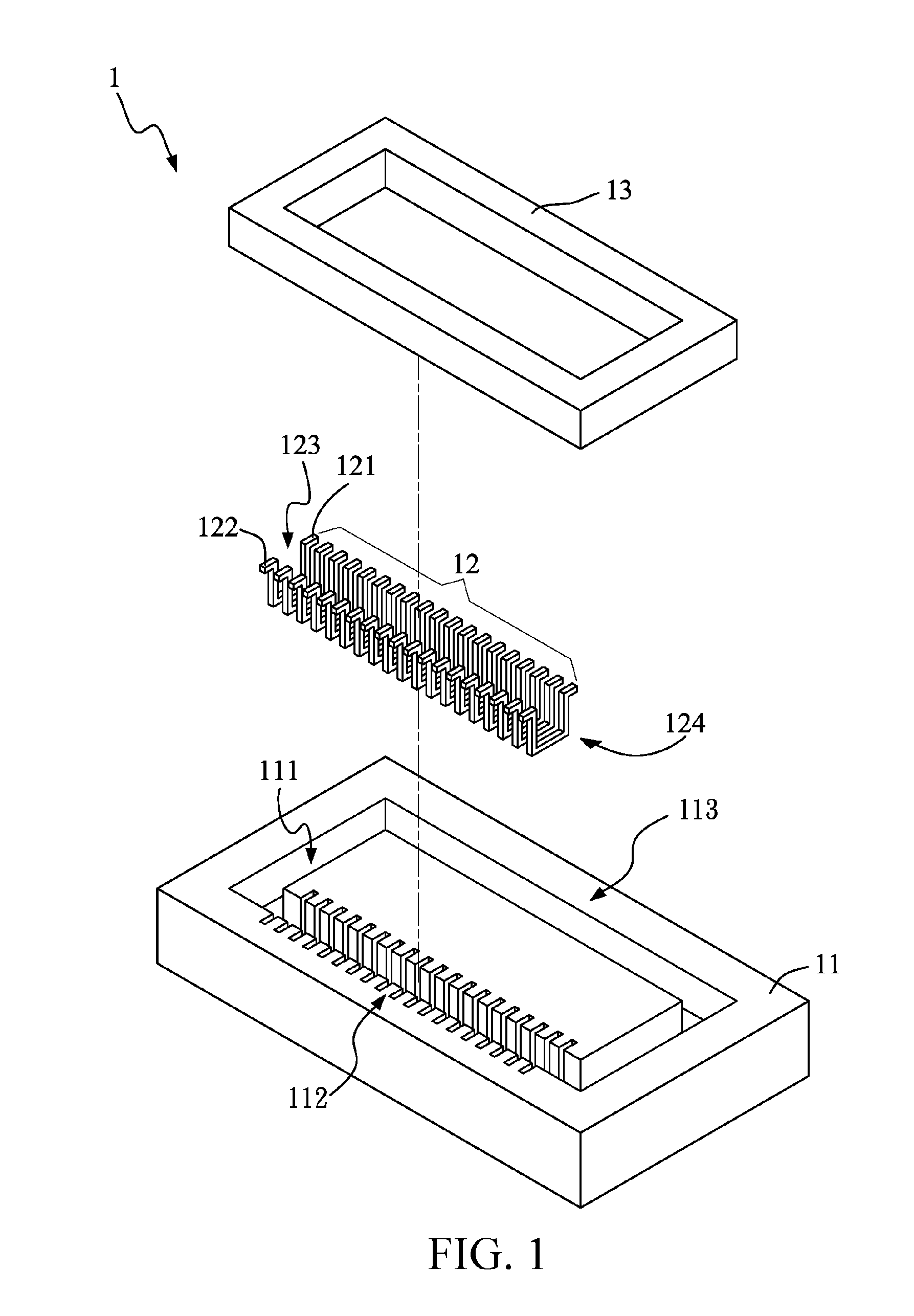
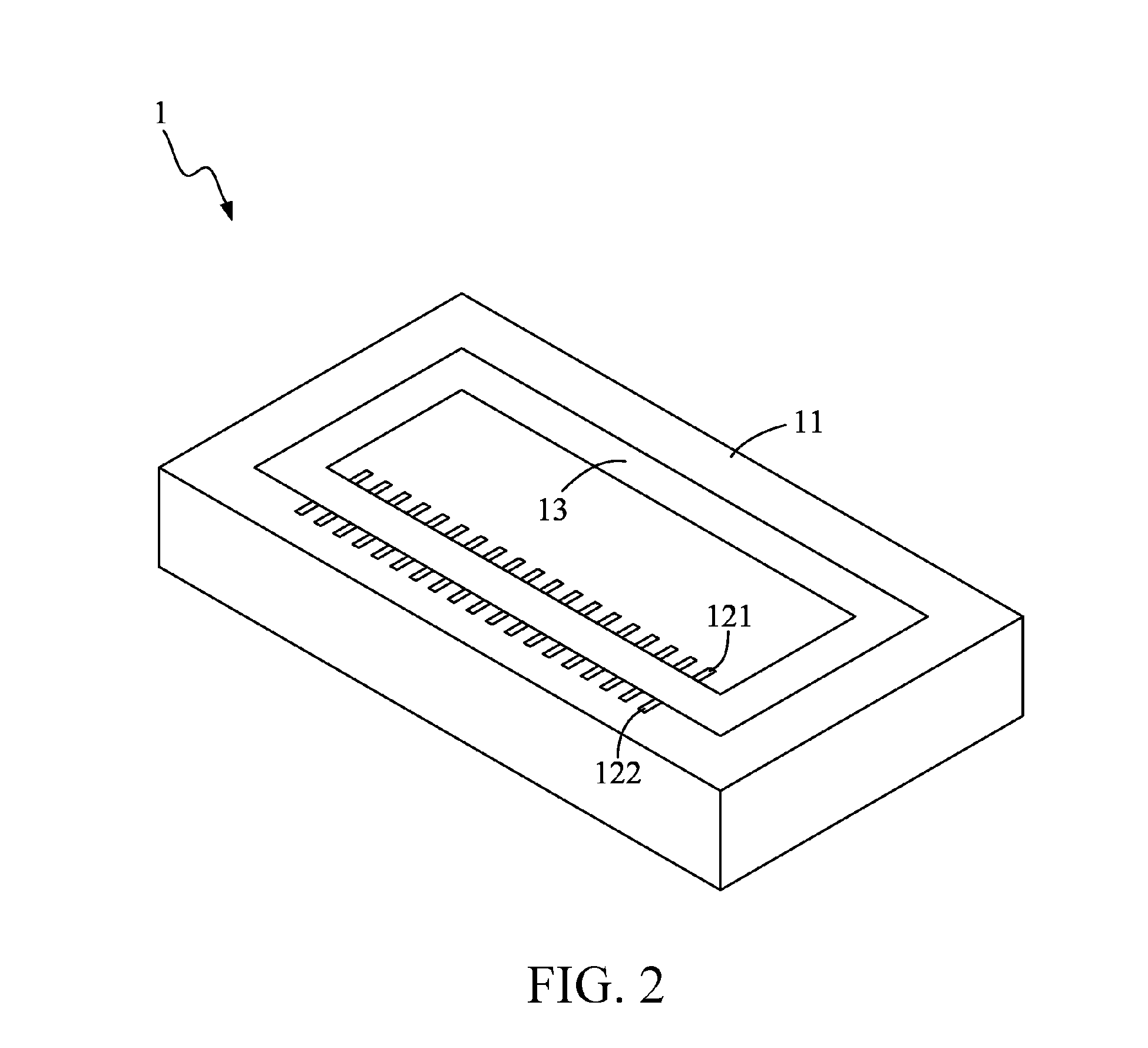
[0029]FIGS. 1-3 are respectively an exploded view, a combined view (1) and a combined view (2) of a first embodiment of the present invention. Please refer to FIGS. 1-3, in which the first embodiment of the present invention includes a substrate 11, a plurality of U-shaped wires 12, and an iron-core device 13. The substrate 11 has a groove 111 divided into a winding area 112 and a non-winding area 113. The U-shaped wires 12 are disposed in the winding area 112 at a fixed space, each U-shaped wire has an opening 123 and a recess 124. A first pin 121 and second pin 122 are respectively arranged at two ends of the opening 123, and the recess 124 is located in the groove 111. The iron-core device 13 is disposed in the groove 111, and passes through the recess 124 of each U-shaped wire 12. As such, a coil surrounding the iron-core device 13 can be formed just by electrically connecting the first pin 121 of the U-shaped wire 12 to the second pin 122 of the abutting U-shaped wire 12. When ...


PUM

PropertyMeasurementUnit
areaaaaaaaaaaa
leakage inductanceaaaaaaaaaa
magnetic flux lossaaaaaaaaaa

Abstract

An iron-core coil assembly is provided, which includes a substrate, a plurality of U-shaped wires, a first pin, a second pin, and an iron-core device. The substrate has a groove divided into a winding area and a non-winding area. The plurality of U-shaped wires is disposed in the winding area at a space from each other, and each U-shaped wire has an opening and a recess. The first pin and the second pin are respectively arranged at two ends of the opening, and the recess is located in the groove. The iron-core device is disposed in the groove, and passes through the recess of each U-shaped wire.

Description

CROSS-REFERENCES TO RELATED APPLICATIONS[0001]This non-provisional application claims priority under 35 U.S.C. §119(a) on Patent Application No. 99214405 filed in Taiwan, R.O.C. on 2010 / 7 / 28, the entire contents of which are hereby incorporated by reference.BACKGROUND OF THE INVENTION[0002]1. Field of Invention[0003]The present invention relates to an iron-core coil assembly, and more particularly to an iron-core coil assembly formed by arranging a groove and U-shaped wires on a substrate, and embedding an iron-core device into the groove.[0004]2. Related Art[0005]An iron-core coil assembly is generally used to fabricate an electronic device or apparatus, such as an inductor, an electrical transformer, and a common mode choke. The traditional process for fabricating the iron-core coil assembly includes winding a wire having an insulating layer coated on its surface (for example, enameled wire), onto a specific winding area of an iron-core device. In order to lower the leakage induct...

Claims


Application Information

Patent Timeline
Patent Type & Authority Applications(United States)
IPC IPC(8): H01F27/30
CPCH01F17/06H01F2027/2814H01F27/306H01F27/2804
Inventor WANG, CHING-SHUNHSIA, CHUN-HUATANG, YUAN-BIN
Owner ADVANCED CONNECTION TECH
Why Eureka
Try Eureka