
Pole lights and dock pole covers with lighting

a technology of dock poles and pole lights, applied in the field of dock poles and portable lighting, to achieve the effect of reducing the chance of tripping over unseen obstacles, convenient implantability, and convenient mobility of safety lights

Inactive Publication Date: 2012-01-26
SCHEFERS ALLEN J +1
View PDF11 Cites 16 Cited by
  • Summary
  • Abstract
  • Description
  • Claims
  • Application Information

AI Technical Summary

Benefits of technology

[0006]The present invention addresses these hazards by providing a means to light previously unlit areas, remote from electric power, through a self-powered mobile safety light mounted to a multi-use pole. The invention consists of a solar-powered safety light which may be attached to a multitude of different utility poles. One embodiment of the utility pole allows the user to slip the utility pole over an existing dock pole so that if a self-powered safety light is positioned on each dock pole on the dock, the boundary of the dock would clearly be defined and the dock surface would be illuminated. Use of the present invention in this manner would reduce the chance of tripping on the dock and increase the viability and location of the dock at night by boat. Furthermore, because of the self-powered safety light is lightweight and easily portable. When finished boating, users may slip the self-powered safety light off the dock pole and carry it with them like a torch to provide lighting along their desired path.
[0008]The utility pole may also be configured with a stake or pointed end, such that the user may stick the pole into the ground. This enables the user to provide fixed lighting for an area or path remote from electric power, thereby reducing the chances of tripping over unseen obstacles. Again, because of the ease in mobility of the safety light, if a user wishes to depart from the remote area, the user may simply remove the self-powered safety light from the ground and carry the light with them along their desired path. This highly adaptable configuration of the safety light's utility pole makes the light readily implantable wherever lighting is needed.

Problems solved by technology

Furthermore, because of the self-powered safety light is lightweight and easily portable.

Method used


Image

  • Pole lights and dock pole covers with lighting
  • Pole lights and dock pole covers with lighting
  • Pole lights and dock pole covers with lighting

Examples


Embodiment Construction

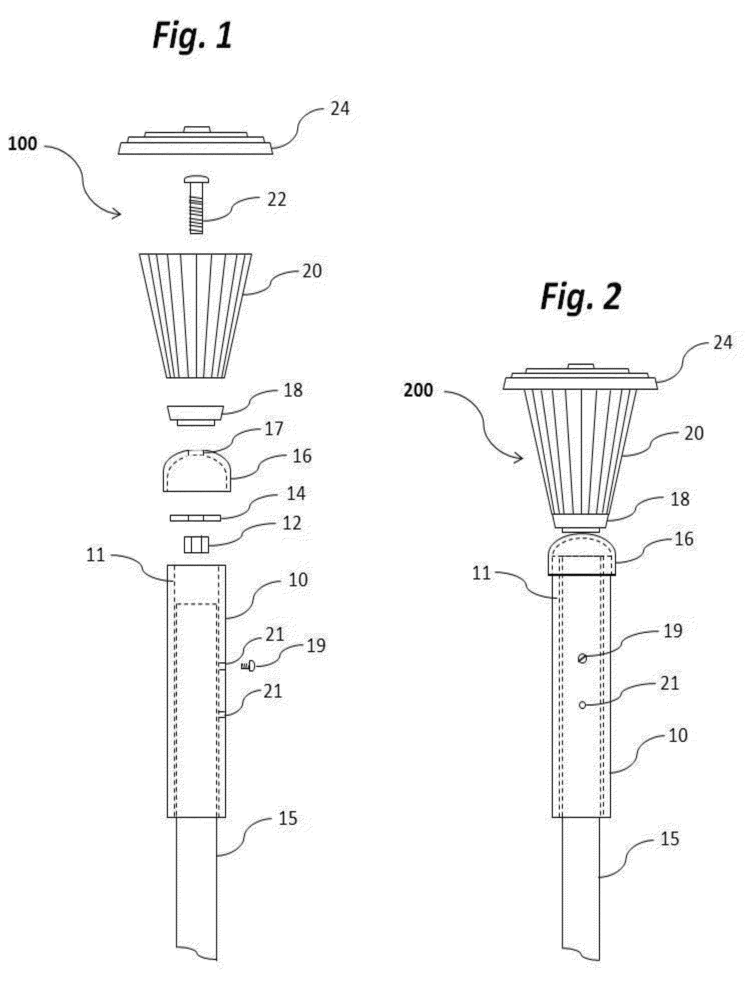
[0017]FIGS. 1 and 2 illustrate an embodiment of a dock pole cover with a self-powered mobile safety light 100 adapted to both cover an existing dock pole 15 and provide solar powered light. Dock pole cover with a self-powered mobile safety light 100 includes: pipe 10, set screw 19, nut 12, washer 14, cap 16, skirt 18, solar powered light 20, bolt 22, and top housing 24.

[0018]The inner diameter 11 of pipe 10 should be larger than the outer diameter of the existing dock pole 15, such that the assembled dock pole cover with a self-powered mobile safety light 200 may be slid onto, and fit over, an existing dock pole 15. As such, the assembled dock pole cover 200 serves as a boat bumper, minimizing damage to both the boat and the dock pole 15 when boats approach or are moored to the dock pole 15. Pipe 10 may consist of a segment of ultraviolet (UV) coated polyvinyl chloride (PVC) piping, as UV coated PVC piping generally is more durable and does not fade or yellow like regular PVC piping...


PUM

PropertyMeasurementUnit
thicknessaaaaaaaaaa
diameteraaaaaaaaaa
diameteraaaaaaaaaa

Abstract

The present invention is a self contained lighting system, including a light member, the light member having at least one light emitting member operably coupled to an ambient light sensor, the light sensor opening a path of electric energy to at least one light emitting member at a first certain sensed level of ambient light and closing the path of electric energy to at least one light emitting member at a second certain sensed level of ambient light, an electric energy storage device operably coupled to the path of electric energy and an electric energy generation device operably coupled to the electric energy storage device, the electric energy generation device for providing electric energy to the electric energy storage device, and a generally thin walled tube being operably coupled to the light member, the tube defining an inner aperture, an opening at the first end of the tube opening to the inner aperture, and at least one threaded, generally transverse bore defined in the thin wall, the at least one bore for threadedly receiving a set screw. A method of forming the self contained lighting system, is further included.

Description

RELATED APPLICATION INFORMATION[0001]This application claims the benefit of U.S. Provisional Application 61 / 366,636, filed Jul. 22, 2010, which is hereby incorporated by reference.FIELD OF THE INVENTION[0002]The present invention generally relates to the field of portable lighting, dock poles, more particularly, the present invention relates to lighting that may be affixed to a dock or impaled in the ground.BACKGROUND OF THE INVENTION[0003]Inadequate lighting on walking paths remote from electrical power is a chronic and potentially serious safety hazard. It is often impractical to run electric power to remote areas; these remote areas may be as far as a camp site located miles away from a source of electric power or as close as the edges of one's own yard. Because these areas are without power, they are often unlit at night. This inadequate lighting can cause a number of safety hazards, the first and foremost being the increased chance of tripping over an unseen obstacle. For examp...

Claims


Application Information

Patent Timeline
Patent Type & Authority Applications(United States)
IPC IPC(8): F21L4/00B23P11/00
CPCE02B3/20F21S2/00F21S8/081F21S8/088F21S9/03F21V21/0824Y10T29/49963F21V21/12F21V21/22F21V23/0464F21V23/06F21W2111/04F21W2131/10F21V21/116Y02B20/72
Inventor SCHEFERS, ALLEN J.REAK, DOUGLAS J.
Owner SCHEFERS ALLEN J
Learn More