
Magnets made from nanoflake precursors

Inactive Publication Date: 2012-01-26
ELECTRON ENERGY CORP
View PDF10 Cites 58 Cited by
  • Summary
  • Abstract
  • Description
  • Claims
  • Application Information

AI Technical Summary

Benefits of technology

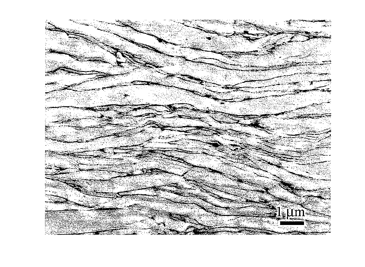
[0035]Wet, high energy ball-milling in non-polar solvents (e.g., heptane) without surfactant results in the formation of magnetically isotropic equiaxed RE-TM microparticles. In contrast, closely packed kebab-like SmCo5 nanoflakes are fabricated by high energy ball-milling in heptane with 15 wt. % oleic acid as surfactant. The increase of the surfactant level from 15 wt. % to 150 wt. % results in well separated, well-defined nanoflakes, rather than the kebab-like SmCo5 nanoflakes observed with 15 wt. % surfactant. These “well separated” SmCo5 nanoflakes are polycrystalline with the crystallite sizes ranging between 4 to 8 nm and indicate enhanced out-of-plane texture and magnetic anisotropy. The intrinsic coercivity of these SmCo5 well separated nanoflakes was 18 kOe.
[0038]The anisotropic, with close-to-bulk magnetic properties, permanent magnet nanoflakes of the present invention bridge the gap toward the nanoparticle-based composite permanent magnets theoretically predicted to double the maximum energy product of the currently available magnets.

Problems solved by technology

Although the precursor RE-TM alloy materials are inherently brittle and not suitable for fabrication into particles with high aspect ratio, surprisingly it has been found that one can control the precursor particle shape by using surfactant assisted, wet, high energy ball milling with or without prior dry high energy ball milling.

Method used


Image

  • Magnets made from nanoflake precursors
  • Magnets made from nanoflake precursors
  • Magnets made from nanoflake precursors

Examples


examples

[0156]The present invention is further described and illustrated by Examples 1 through 11 set forth below and detailed in FIGS. 1 through 21 of the Drawings.

examples 1 and 2

Introduction to Examples 1 and 2

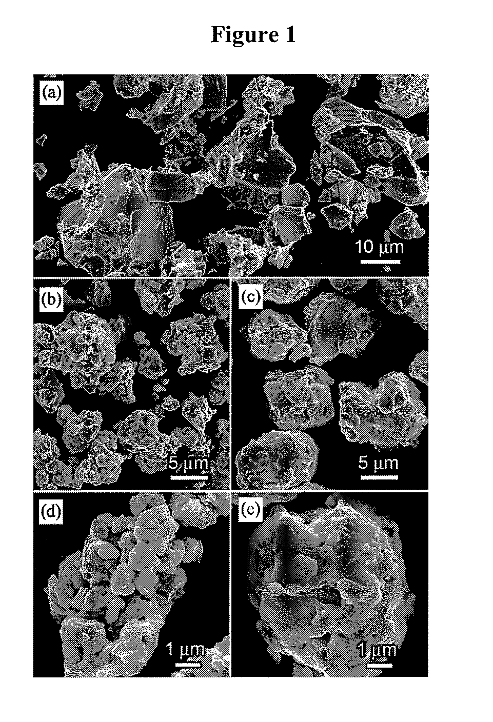
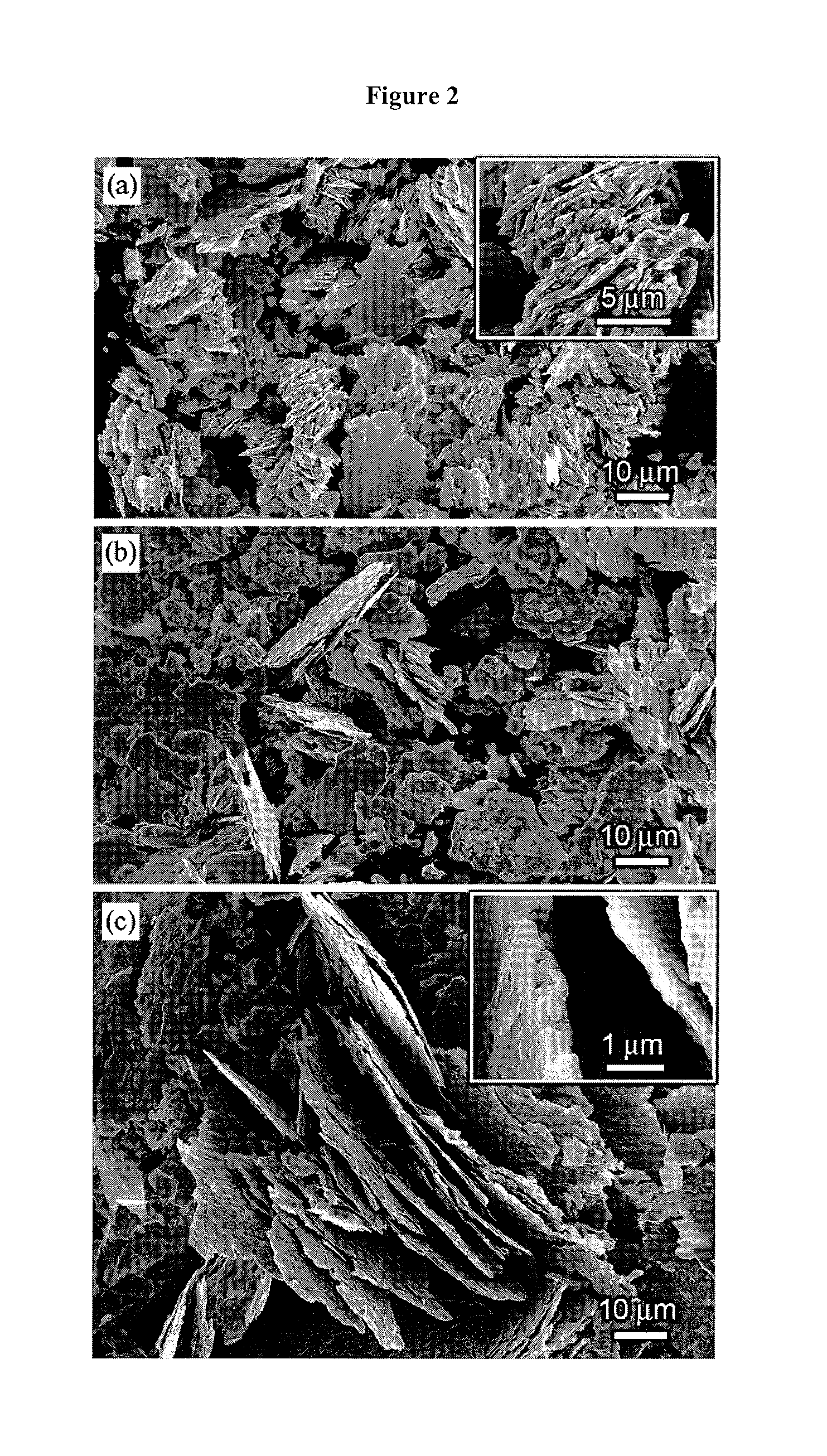
[0157]Examples 1 and 2 are further illustrated in FIGS. 1 through 3 of the drawings. In examples 1 and 2, brittle SmCo5 alloys were subjected to successive dry and wet high energy ball milling in the presence of a surfactant. Surprisingly, the evolution of nanoflakes-shaped particles from these nominally brittle alloys which were wet-milled after prolonged dry milling indicated malleability similar to that of ductile materials. This malleability / ductility induced by nanostructure is particularly unexpected. For example, SmCo5 crushed ingots subjected to high energy ball-milling in heptane without surfactant transformed into rather equiaxed particles.

[0158]Alloys with the nominal composition Sm17Co83 (in at. %) which corresponds to SmCo5 formula, were prepared from pure components by arc-melting. In order to offset oxidation of the RE during milling, the SmCo5 alloys were made with 2 extra at. % (relative) of Sm to compensate for the evaporation loss o...

example 1

[0160]The first example describes the evolution of SmCo5 particles through dry, in Ar, high energy ball milling, which is the first step, prior to wet, surfactant assisted high energy ball-milling, in the fabrication of SmCo5 nanoflakes of the invention. During the dry high energy ball milling, the SmCo5 powders reveal a very rapid decline of the average particle size in the first minutes of the milling, as the cast material breaks up. Powders dry-milled for 1 min. are shown in FIG. 1(a); they consist mostly of non-agglomerated particles 1 to 30 μm in size with characteristically polygonal shapes and sharp edges. After 5 min. of milling, only few separate particles with these features can still be found, as the smallest particles are being increasingly coalesced with each other and with the bigger particles. As shown in FIG. 1(b) & (d), the newly assembled particles (agglomerates) appear “loose” and their size varies broadly from few microns to tens of microns. After prolonged milli...


PUM

PropertyMeasurementUnit
Timeaaaaaaaaaa
Percent by atomaaaaaaaaaa
Metallic bondaaaaaaaaaa

Abstract

RE-TM based permanent magnets (single phase, hybrid, laminated or polymer bonded magnets) fabricated by using nanoflakes produced by surfactant assisted, wet, high energy ball-milling, with or without prior dry high energy ball-milling, where RE represents rare earth elements and TM represents transition metals.

Description

STATEMENT OF GOVERNMENT SUPPORT[0001]This invention was made with government support under Award No. IIP-0848996 awarded by the National Science Foundation. The United States government has certain rights in the invention.BACKGROUND OF THE INVENTION[0002]The present invention is directed to bulk magnets comprising nanoflakes fabricated by surfactant-assisted, wet, high energy balling-milling various precursors. The nanoflakes may consist of different metallic phases belonging to the same group of magnetic materials, such as hard magnetic or soft magnetic, and a non-magnetic metallic or polymer binder phase.[0003]High energy ball milling has been used for manufacturing nanocrystalline and amorphous materials, including rare earth-transition metal (RE-TM) permanent magnet materials, while independently, surfactants have been used to control the size, shape and properties of metal or ceramic powders during the low energy conventional milling, as described in the references:[0004]Haneda...

Claims


Application Information

Patent Timeline
IPC IPC(8): H01F7/02B02C17/00B22F3/10B02C23/18B22F1/00B22F3/02B22F1/054
CPCB22F1/0018B22F2001/0033H01F7/02H01F1/0571H01F1/0551C22C2202/02C22C1/0441B82Y30/00B22F2999/00B22F2998/10B22F2009/043B22F3/10B22F3/105B22F3/14B22F3/225B22F1/0551B22F1/054
Inventor GABAY, ALEXANDERCUI, BAOZHIMARINESCU, MELANIALIU, JINFANGHADJIPANAYIS, GEORGE C.
Owner ELECTRON ENERGY CORP
Learn More