Spin mosfet and reconfigurable logic circuit

a logic circuit and spin mosfet technology, applied in the direction of pulse technique, separation process, instruments, etc., can solve the problems of difficult field shift adjustment, magnetic recording layer, and inability to perform shift adjustmen

Inactive Publication Date: 2012-01-26
KK TOSHIBA
View PDF46 Cites 10 Cited by
  • Summary
  • Abstract
  • Description
  • Claims
  • Application Information

AI Technical Summary

Benefits of technology

[0013]The present invention has been made in view of these circumstances, and an object thereof is to provide a spin MOSFET that can reduce the influence of a leakage magnetic field on adjacent transistors, enable shift adjustment, and restrain spin relaxation in the channel region, even where vertical magnetization films are used in the ferromagnetic material of the MTJ in the source / drain region. The present invention also aims to provide a reconfigurable logic circuit.

Problems solved by technology

In a case where vertical magnetization films are used in the MTJ of the source or drain region, however, a leakage magnetic field generated from the fixed magnetization layer of the MTJ affects the magnetic recording layer, and shift adjustment cannot be performed, as will be described below.
However, a spin MOSFET having a lateral structure has the following problems: difficult field shift adjustment, influence of a leakage magnetic field on adjacent transistors, and accelerated spin relaxation in the semiconductor region to be the channel region due to the leakage magnetic field.

Method used


Image

  • Spin mosfet and reconfigurable logic circuit
  • Spin mosfet and reconfigurable logic circuit
  • Spin mosfet and reconfigurable logic circuit

Examples


first embodiment

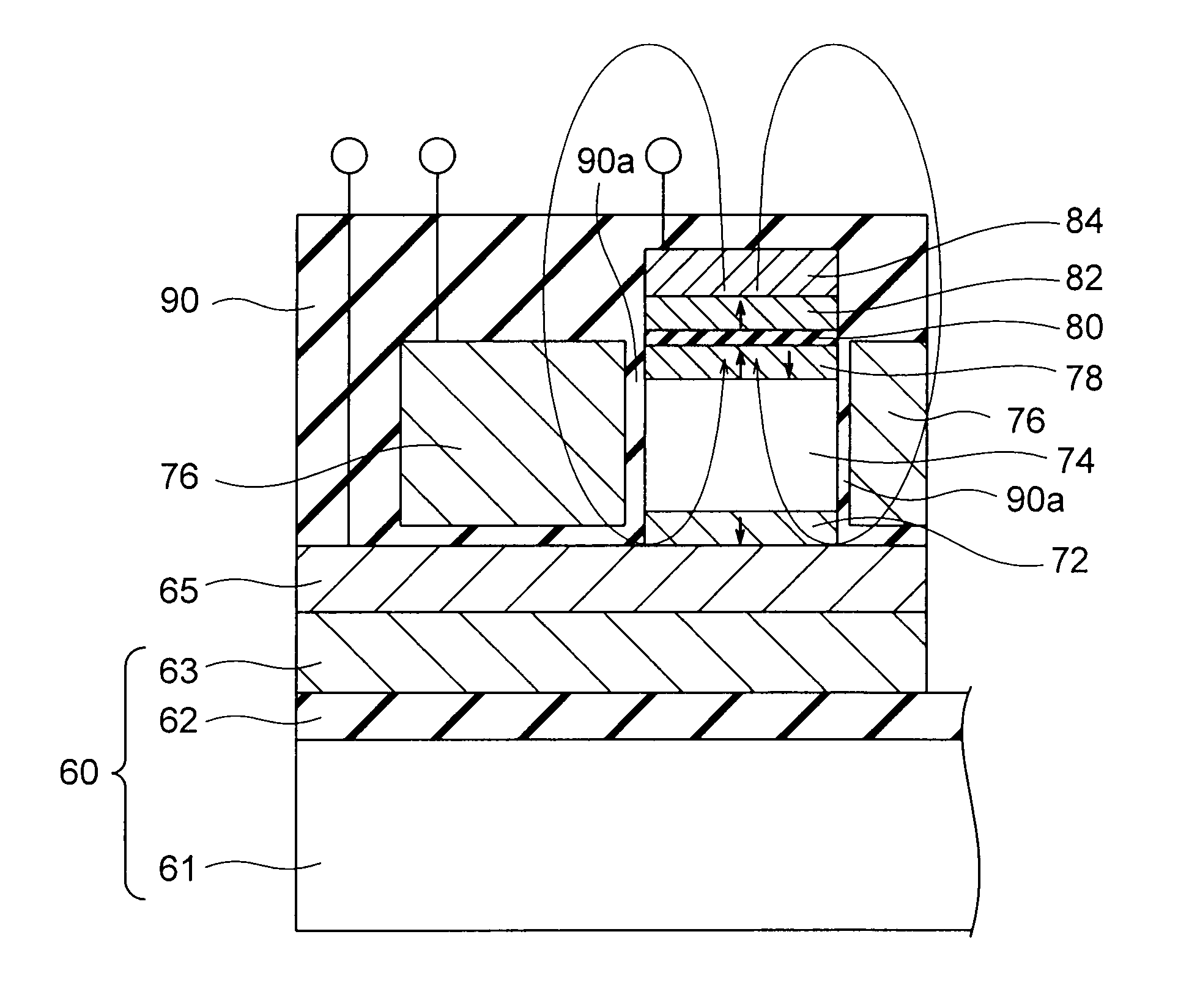
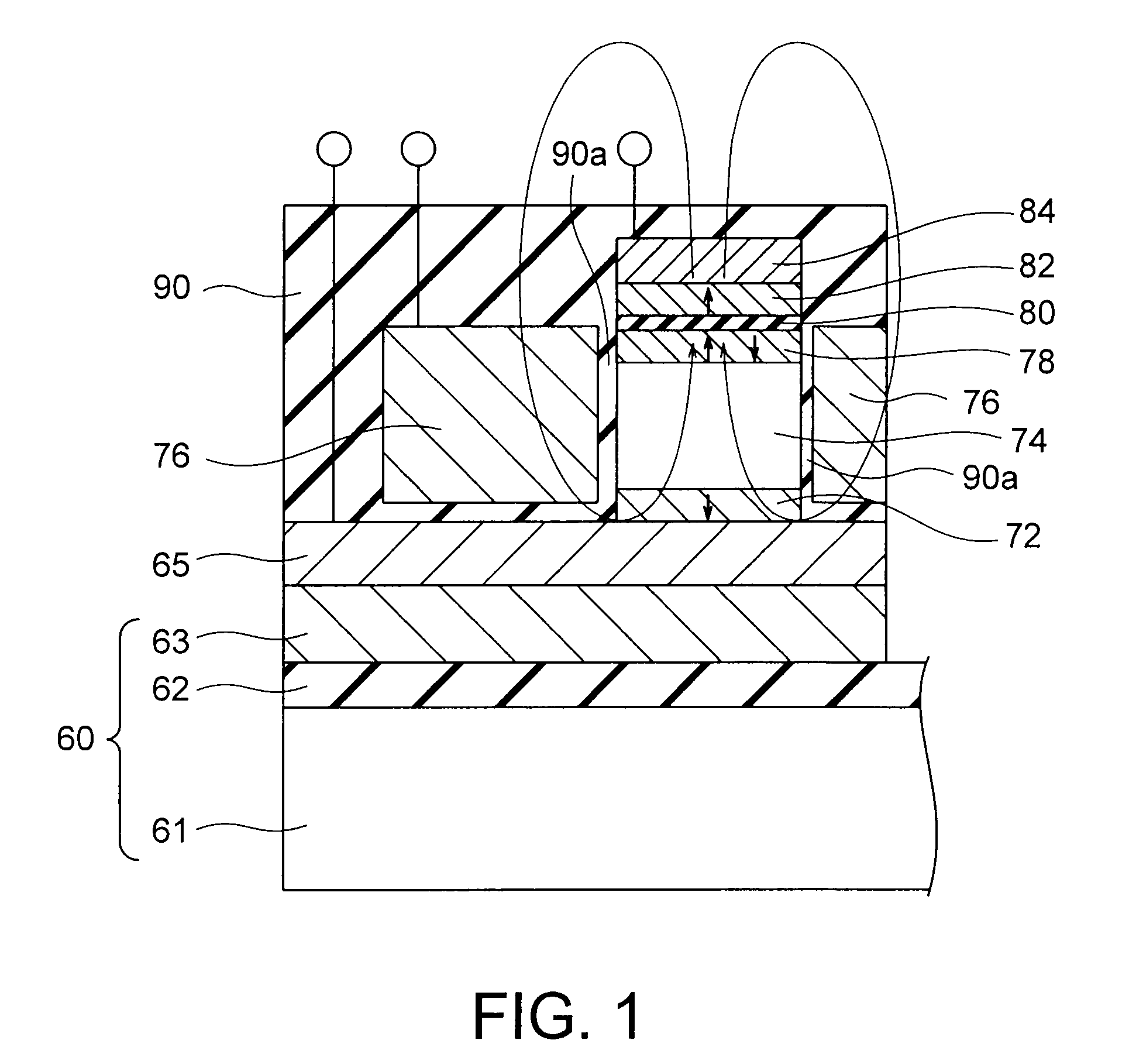
[0049]FIG. 1 shows a spin MOSFET according to a first embodiment of the present invention. The spin MOSFET of this embodiment is a vertical type spin MOSFET, and is formed on a SOI substrate 60 that includes a supporting substrate 61 made of Si, a buried oxide film 62, and a SOI (Silicon On Insulator) layer 63. The spin MOSFET may be formed on a Si bulk substrate, instead of a SOI substrate. A base layer 65 is formed on the SOI layer 63. A ferromagnetic layer 72 that has magnetization substantially perpendicular to a film plane and has a fixed magnetization direction is formed on the base layer 65. In this specification, a “film plane” of a ferromagnetic layer is an upper face of the ferromagnetic layer. A channel layer 74 that is formed from p-type semiconductor crystals is formed on the ferromagnetic layer 72. A free layer 78 that has a variable magnetization direction and is formed of a ferromagnetic layer is formed on the channel layer 74. A tunnel barrier 80 is formed on the fr...

second embodiment

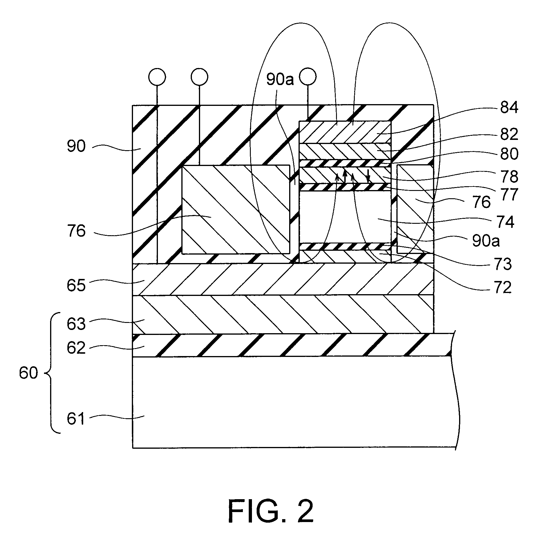
[0056]FIG. 2 is a spin MOSFET according to a second embodiment of the present invention. The spin MOSFET of this embodiment is a vertical spin MOSFET, and is the same as the spin MOSFET of the first embodiment shown in FIG. 1, except that a tunnel barrier 73 is provided between the channel layer 74 formed from semiconductor crystals and the ferromagnetic layer 72, and a tunnel barrier 77 provided between the channel layer 74 and the free layer 78. If tunnel barriers made of a material such as MgO that can epitaxially grow even if the channel layer 74 is made of Ge or GaAs are used as the tunnel barriers 73 and 77, the tunnel barriers 73 and 77 can also serve as diffusion barriers, and advantageously improve the resistance to device pressure. In this embodiment, a stacked structure that is formed of the ferromagnetic layer 72, the tunnel barrier 73, the channel layer 74 formed from semiconductor crystals, the tunnel barrier 77, the free layer 78, the tunnel barrier 80, the ferromagne...

third embodiment

[0059]FIG. 3 is a cross-sectional view of a spin MOSFET according to a third embodiment of the present invention. The spin MOSFET of this embodiment is a lateral n-type spin MOSFET that is formed in a device region 3 of a p-type semiconductor substrate 2. This device region 3 is a semiconductor region divided by device-insolating insulating films 4. The semiconductor region may be part of a semiconductor substrate, or may be a well region formed on a semiconductor substrate. Alternatively, the semiconductor region may be a SOI layer on a SOI substrate. In this specification, the device region 3 may be a semiconductor region that is part of a p-type semiconductor substrate, or may be a p-well region formed on an n-type substrate. In this device region 3, an n-type impurity diffusion region 6a and an n-type impurity diffusion region 6b are formed at a distance from each other. An n+-impurity diffusion region 7a and an n+-type impurity diffusion region 7b having higher density than the...


PUM


Abstract

A spin MOSFET includes: a first ferromagnetic layer provided on a semiconductor substrate, and having a fixed magnetization direction perpendicular to a film plane; a semiconductor layer provided on the first ferromagnetic layer, including a lower face opposed to the upper face of the first ferromagnetic layer, an upper face opposed to the lower face, and side faces different from the lower and upper faces; a second ferromagnetic layer provided on the upper face of the semiconductor layer, and having a variable magnetization direction perpendicular to a film plane; a first tunnel barrier provided on the second ferromagnetic layer; a third ferromagnetic layer provided on the first tunnel barrier; a gate insulating film provided on the side faces of the semiconductor layer; and a gate electrode provided on the side faces of the semiconductor layer with the gate insulating film being interposed therebetween.

Description

CROSS-REFERENCE TO RELATED APPLICATION[0001]This application is a division of and claims the benefit of priority under 35 U.S.C. §120 from U.S. Ser. No. 12 / 725,561 filed Mar. 17, 2010, and claims the benefit of priority under 35 U.S.C. §119 from Japanese Patent Application No. 2009-74785 filed Mar. 25, 2009, the entire contents of each of which are incorporated herein by reference.BACKGROUND OF THE INVENTION[0002]1. Field of the Invention[0003]The present invention relates to a spin MOSFET and a reconfigurable logic circuit.[0004]2. Related Art[0005]In recent years, MRAM (Magnetic Random Access Memory) with a MTJ (Magnetic Tunnel Junction) having a tunnel barrier layer interposed between two vertical magnetization films has been drawing attention, for its lower spin injection current density and excellent thermal stability. In this specification, a “vertical magnetization film” is a ferromagnetic film that has a magnetization direction (a magnetization easy-axis direction) substanti...

Claims


Application Information

Patent Timeline
Patent Type & Authority Applications(United States)
IPC IPC(8): H03K19/173H01L29/82
CPCG11C11/16H01L43/10H01L43/02G11C11/161G11C11/1673G11C11/1675G11C11/1695H01L29/66984H01L29/0843H01L29/0895H01L28/00B01D53/1493B01D53/62H10N50/80H10N50/85
Inventor SAITO, YOSHIAKISUGIYAMA, HIDEYUKIINOKUCHI, TOMOAKIMARUKAME, TAKAOISHIKAWA, MIZUE
Owner KK TOSHIBA
Why Eureka
Try Eureka