
Deepwater oil recovery process

a deepwater oil recovery and process technology, applied in separation processes, multi-stage water/sewage treatment, borehole/well accessories, etc., can solve the problems of contaminating the coast line, unable to accurately predict the volume of oil released, and the oil spill described as the largest environmental disaster

Inactive Publication Date: 2012-01-26
ECOSPHERE TECH
View PDF12 Cites 6 Cited by
  • Summary
  • Abstract
  • Description
  • Claims
  • Application Information

AI Technical Summary

Benefits of technology

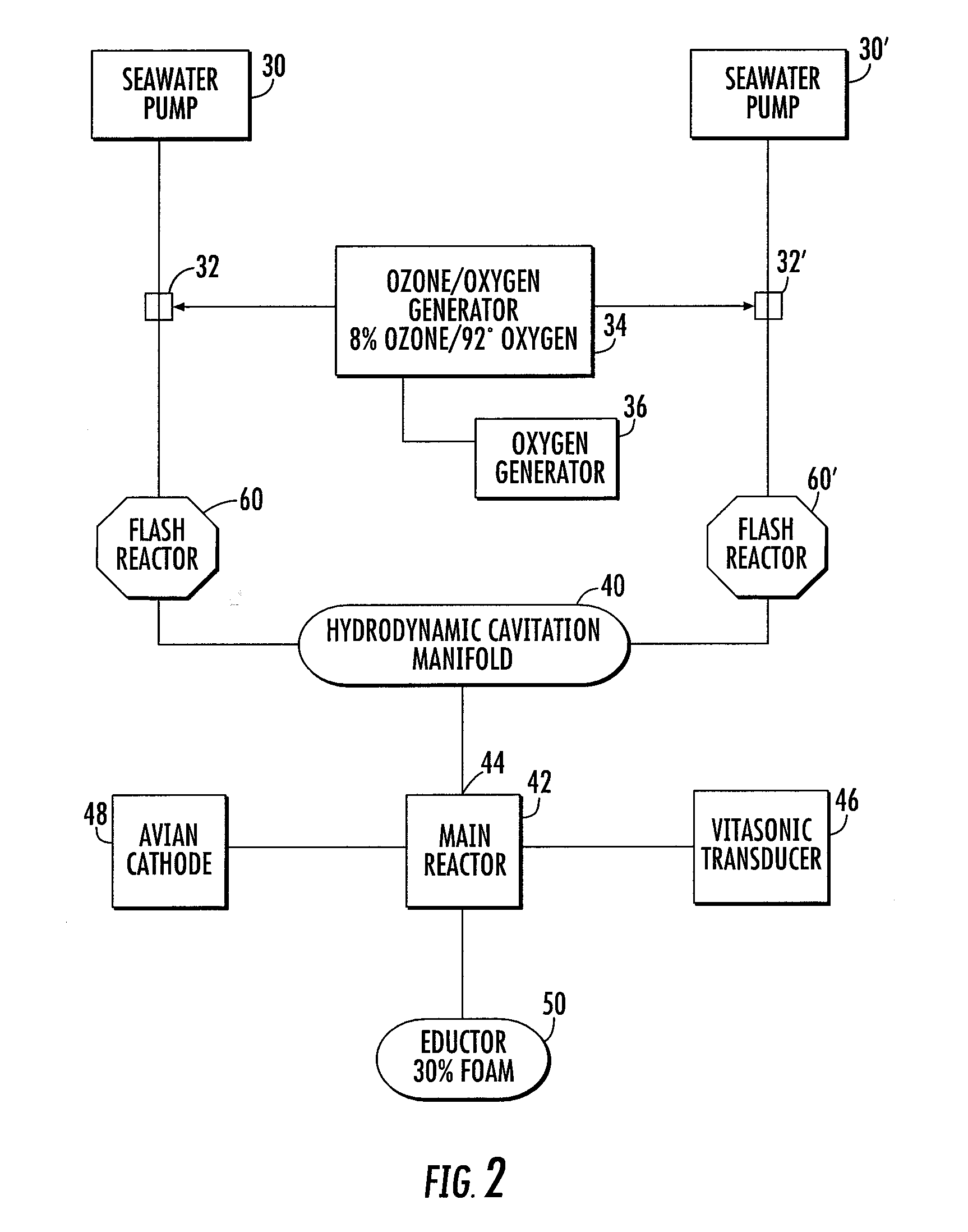
The invention is a method for treating deep water oil spills using ozone / oxygen gas mixed with seawater and a tank mixing eductor to create small oil droplets. The droplets react with the ozone / oxygen in the seawater to form larger bubbles, which rise faster in the sea and help to attract and absorb the oil. The invention also includes a two-step remediation process, an apparatus for converting asphaltenes to lower molecular weight compounds and coke, and an apparatus for reacting directly with double bonds in petroleum compounds. The invention also aims to make crude oil more bio-degradable.

Problems solved by technology

On Apr. 20, 2010, a semi-submersible exploratory offshore drilling rig in the Gulf of Mexico exploded resulting in an oil spill described as the largest environmental disaster in U.S. history.
Due to the location of the oil leak, nearly one mile beneath the surface of the water, accurate predictions of the volume of oil released is not possible.
No matter what the actual amount of oil has leaked, an oil spill can contaminate the coast lines and threatens wildlife refuges, ecologically sensitive areas, fisheries, as well as densely populated waterfronts.
Efforts to address oil spills include controlled burns which have limited success and pose yet another ecological problem.
However, the oil disperses very quickly making containment difficult, even when the seas are calm.
However, oil spill dispersants do not reduce the total amount of oil entering the environment.
Corexit® and other dispersants, made up of classified chemicals may result in a devastating effect in the Gulf.
In addition, the dispersants are made up of a classified chemical so it is not possible to access the danger they pose when the ingredients are kept confidential.

Method used


Image

  • Deepwater oil recovery process
  • Deepwater oil recovery process
  • Deepwater oil recovery process

Examples


Embodiment Construction

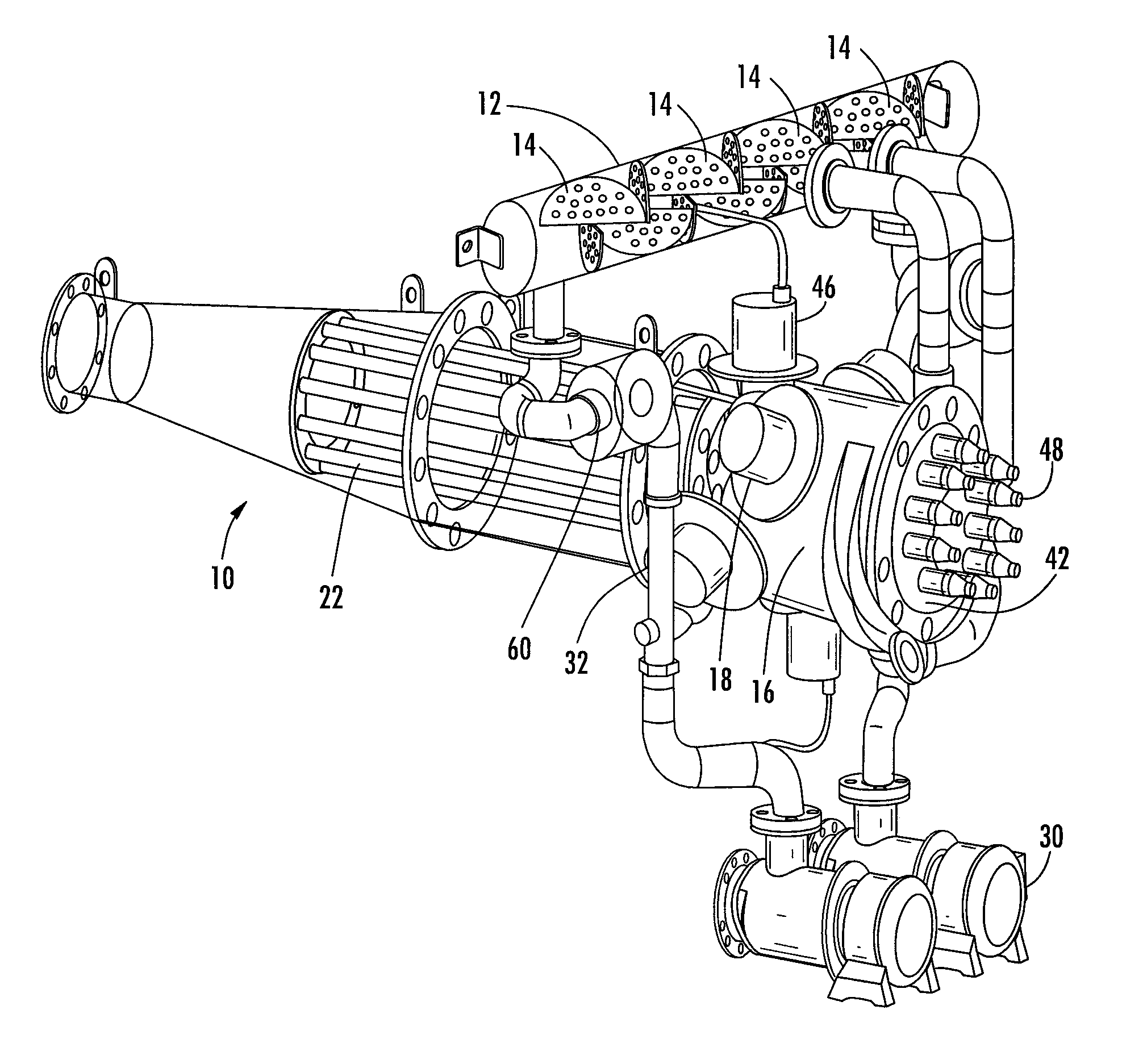
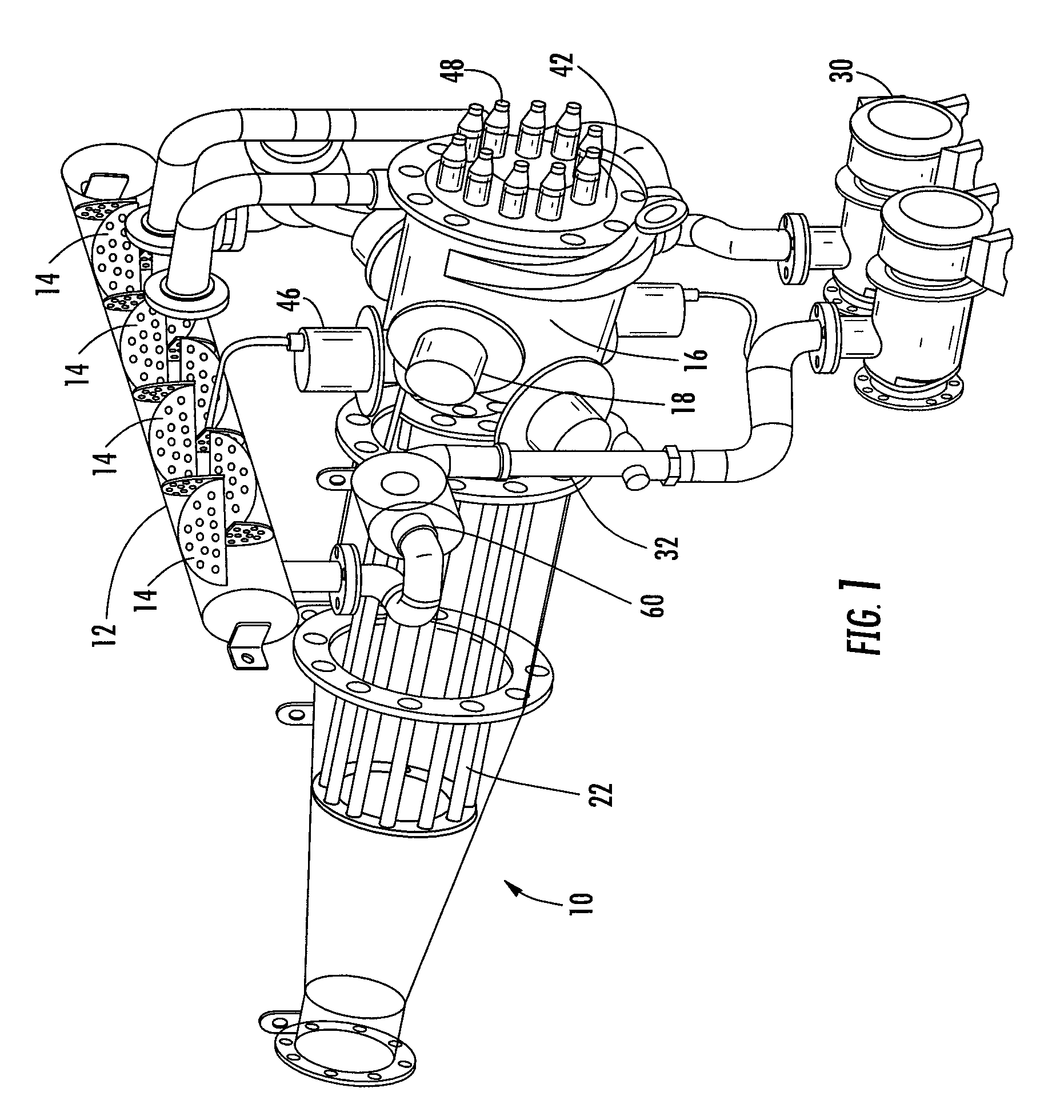
[0027]For use by example, the previously mentioned situation consists of an oil plume having about a 3000 GOR with the oil venting into seawater at about 2270 psi and 33 F. Methane rich gas forms gas hydrates in this environment at a specific gravity of 0.9. The degassed oil plume has density close to about 0.8 specific gravity and close to about 120 cp viscosity. The addition of a dispersant causes significant (about 4 to 1) emulsification of seawater and oil. It should be noted that to bio-degrade 10,000 bbls of oil by weathering would require approximately 40 square miles of seawater above the thermocline. Thermochimica Acta Volume 312, Issue 1-2, Mar. 23, 1998, Pages 87-93, shows that the heat of adsorption for oxygen gas is 125 kcal / gmol for the unsaturated carbon sites. This is an exothermic reaction, not oxidation. It is adsorption of an oxygen molecule on an unsaturated site in the asphaltene molecule which is similar to hydrogen bonding of sticky maple syrup on a plate surf...


PUM

PropertyMeasurementUnit
oil flow ratesaaaaaaaaaa
pressureaaaaaaaaaa
specific gravityaaaaaaaaaa

Abstract

Ozone / oxygen gas is mixed with treated seawater at 30% quality foam and injected to the wellhead at the sea floor. At the seafloor, a tank mixing eductor would be used to mix high pressure oxygen bubbles with the oil contaminated seawater by shearing the oil globs into small oil droplets allowing the new surface area to immediately react with the dissolved ozone / oxygen in the seawater. The ozone / oxygen admixture creating an attraction force between the droplets and the oxygen bubbles. As the droplets and bubble rise, they form larger spherical top-hat bubbles that rise faster in the seawater. In the preferred embodiment, the eductor employs a cone shape flow to direct a significant amount of the oil plume into a predictable area that can then be skimmed mechanically for harvesting or destruction.

Description

CROSS-REFERENCE TO RELATED APPLICATIONS[0001]The instant application claims the priority date of U.S. Provisional Patent Application 61 / 353,041 filed Jun. 9, 2010 the contents of which are incorporated herein by reference. This application is related to U.S. patent application entitled “Apparatus for Treating Fluids”, filed as provisional No. 61 / 495,237 on Jun. 9, 2011 which is a continuation-in-part of U.S. patent application Ser. No. 13 / 019,113, entitled “Transportable Reactor Tank”, filed Feb. 1, 2011, which is a continuation-in-part of U.S. patent application Ser. No. 12 / 765,971, entitled “Improved Reactor Tank”, filed Apr. 23, 2010, which is a continuation-in-part of U.S. patent application Ser. No. 12 / 399,481, entitled “Enhanced Water Treatment for Reclamation of Waste Fluids and Increased Efficiency Treatment of Potable Waters”, filed Mar. 6, 2009, now U.S. Pat. No. 7,699,988, issued Apr. 20, 2010, which is a continuation-in-part of U.S. patent application Ser. No. 12 / 184,716...

Claims


Application Information

Patent Timeline
Patent Type & Authority Applications(United States)
IPC IPC(8): C02F1/40C02F9/00C02F1/78C02F1/24C02F1/36
CPCC01B11/062E21B43/0122C01B13/10C01B15/01C02F1/006C02F1/24C02F1/34C02F1/36C02F1/4672C02F1/727C02F1/78C02F2101/32C02F2103/007C02F2103/06C02F2201/784C02F2301/024C02F2305/023C01B13/02
Inventor MCGUIRE, DENNISJAKHETE, SANJEEV
Owner ECOSPHERE TECH
Learn More