Electric power tool
- Summary
- Abstract
- Description
- Claims
- Application Information
AI Technical Summary
Benefits of technology
Problems solved by technology
Method used
Image
Examples
first embodiment
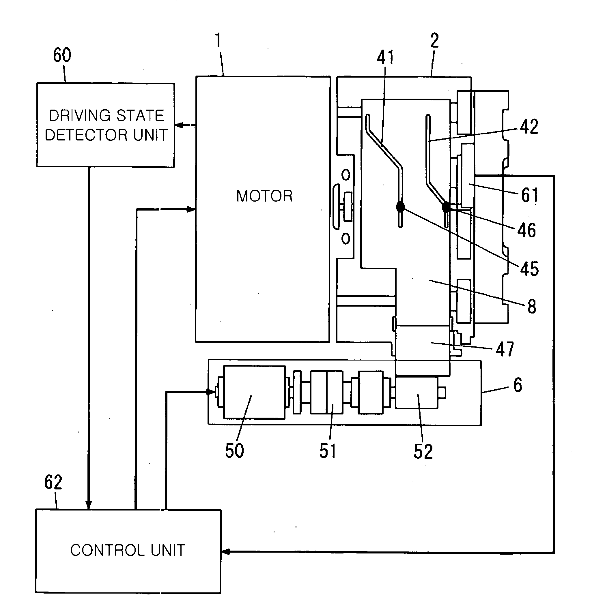
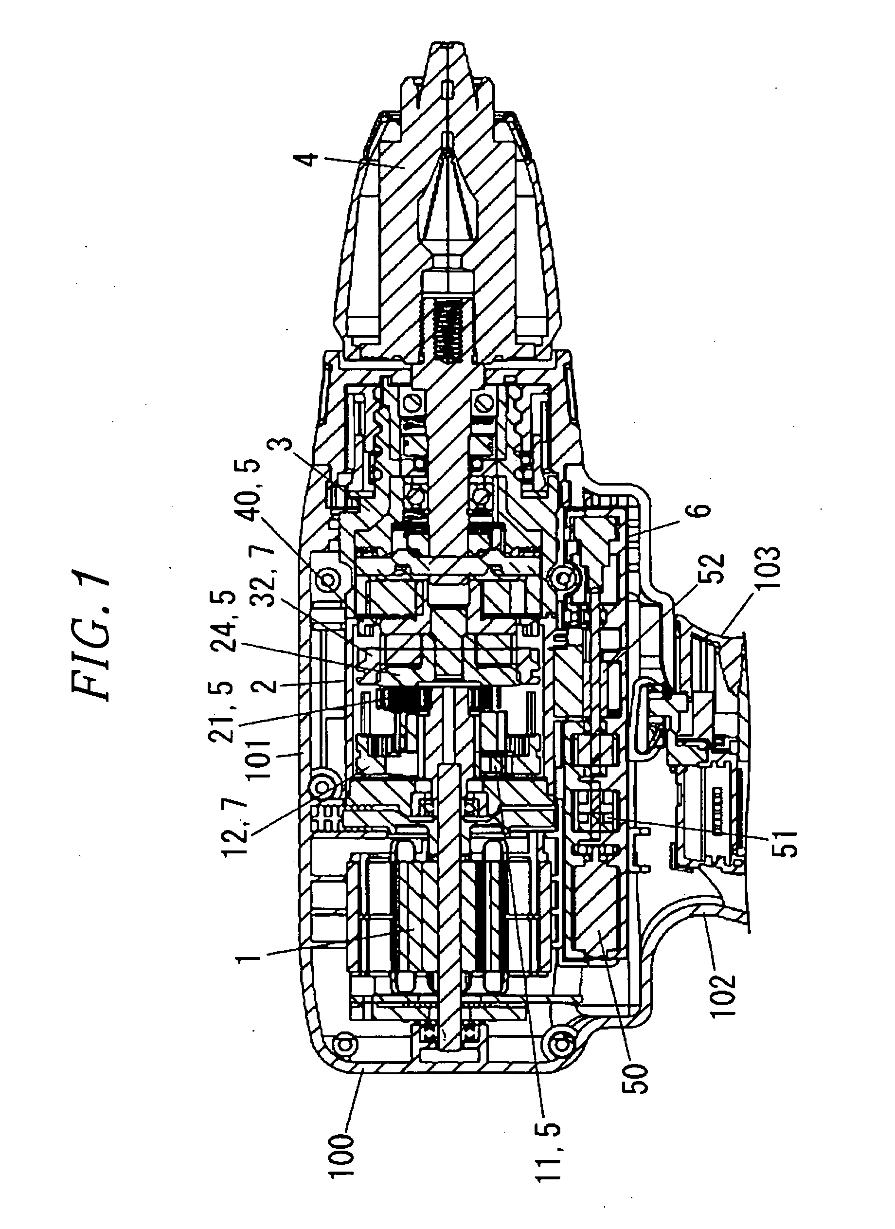
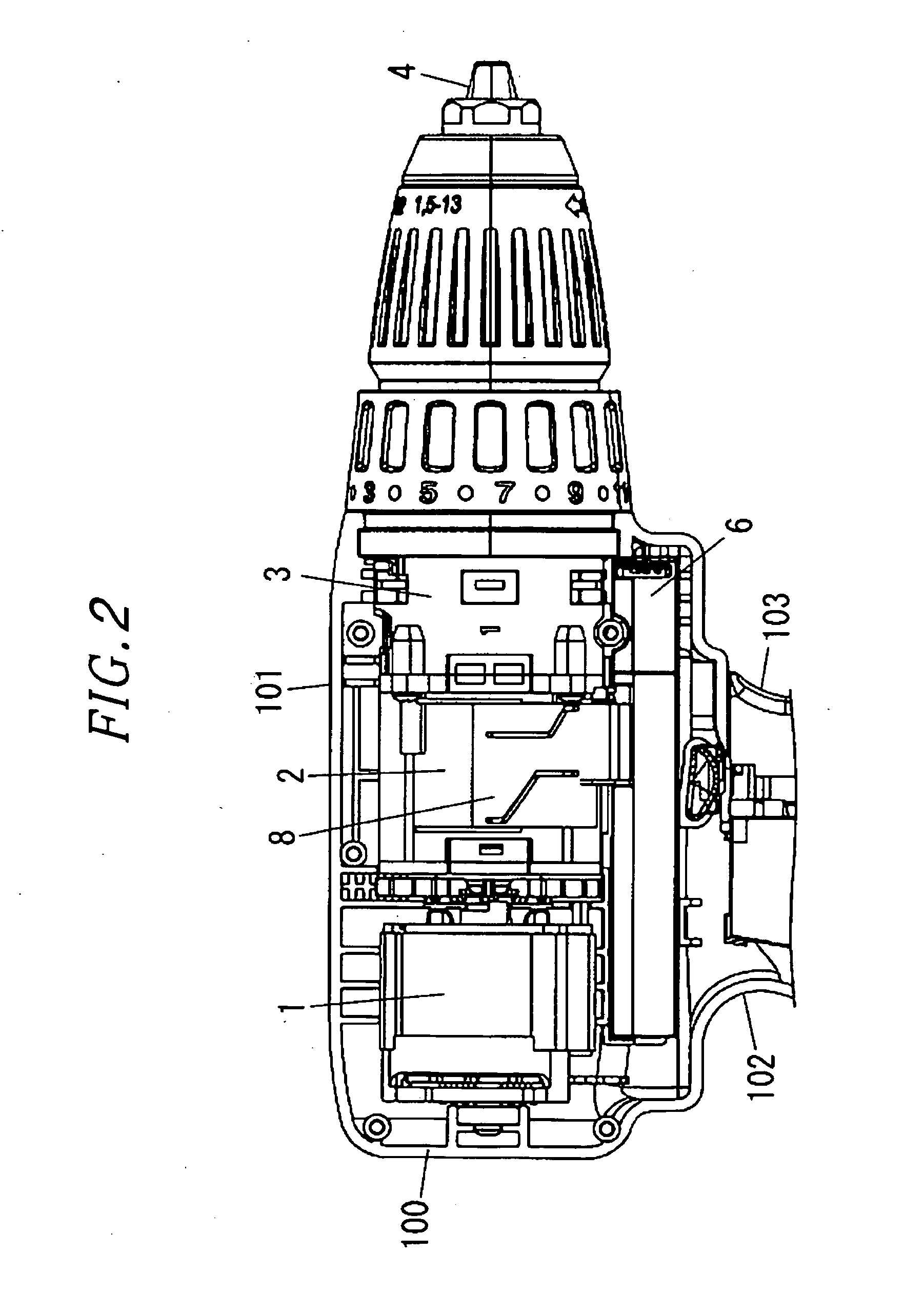
[0040]FIGS. 1 through 3 show an electric power tool in accordance with a first embodiment of the present invention. The electric power tool of the present embodiment includes a motor (main motor) 1 as a drive power source, a speed reduction mechanism 2 for transferring the rotational power of the motor 1 at a reduced speed, a drive power delivery unit 3 for delivering the rotational power transferred from the speed reduction mechanism 2 to an output shaft 4, and a trunk housing 101 for accommodating the motor 1, the speed reduction mechanism 2 and the drive power delivery unit 3. A grip housing 102 extends from the trunk housing 101. A trigger switch 103 is retractably attached to the grip housing 102. The trunk housing 101 and the grip housing 102 make up a body housing 100 of the electric power tool.
[0041]A shift actuator 6 is arranged within the trunk housing 101 in a parallel relationship with the motor 1 and the speed reduction mechanism 2. The shift actuator 6 is of a rotary t...
second embodiment
[0104]In the electric power tool of the present embodiment, the drive control of the shift actuator 6 is changed if the gears do not successfully engage with each other and the shift operation fails. This realizes a smooth and stable automatic shift operation and restrains wear or damage of gears otherwise caused by collision. The present embodiment differs from the first embodiment in the method of changing the drive control of the shift actuator 6.
[0105]Specifically, if the detection result of the slide position detector unit 61 reveals that the changeover member 7 fails to slide to a desired target position, the control unit 62 changes the drive control of the shift actuator 6 so that the rotational power of the motor 50 of the shift actuator 6 can be increased. In other words, the changeover member 7 and the gear member 5 are made easy to mesh with each other by changing the sliding drive power with which the changeover member 7 is slid by the shift cam plate 8.
[0106]The sliding...
third embodiment
[0107]In the electric power tool of the present embodiment, the relative rotational position of the changeover member 7 and the gear member 5 is changed if the gears do not successfully engage with each other and the shift operation fails. This realizes a smooth and stable automatic shift operation and restrains wear or damage of gears otherwise caused by collision. The present embodiment differs from the first embodiment in the method of changing the control in the case of the failure of the shift operation.
[0108]Specifically, if it is determined that the changeover member 7 fails to slide to a desired target position and the motor is hardly driven, the control unit 62 changes the rotational power of the motor 1 while maintaining the operation of the shift actuator 6. In other words, such control is carried out if the detection result of the slide position detector unit 61 reveals that the changeover member fails to slide to a desired target position while the shift actuator 6 is d...
PUM
| Property | Measurement | Unit |
|---|---|---|
| Power | aaaaa | aaaaa |
| Speed | aaaaa | aaaaa |
| Acceleration | aaaaa | aaaaa |
Abstract
Description
Claims
Application Information
 - R&D
- Intellectual Property
- Life Sciences
- Materials
- Tech Scout
- Unparalleled Data Quality
- Higher Quality Content
- 60% Fewer Hallucinations
Browse by: Latest US Patents, China's latest patents, Technical Efficacy Thesaurus, Application Domain, Technology Topic, Popular Technical Reports.
© 2025 PatSnap. All rights reserved.Legal|Privacy policy|Modern Slavery Act Transparency Statement|Sitemap|About US| Contact US: help@patsnap.com


