LED street lamp

a technology of led light source and led housing, which is applied in the direction of lighting and heating equipment, semiconductor devices for light sources, and lighting support devices. it can solve the problems of obstructing the heated air in the lamp housing, increasing the operating heat, and increasing so as to reduce the thickness of the housing and avoid obstructing the airflow. , the effect of increasing the speed of airflow

Inactive Publication Date: 2012-01-12
WANG CHIN WEN +1
View PDF4 Cites 28 Cited by
  • Summary
  • Abstract
  • Description
  • Claims
  • Application Information

AI Technical Summary

Benefits of technology

[0008]The objective of the present invention is to provide a LED street lamp having corresponding heat dissipating holes on both the top and bottom shell so as to allow heated air in the lamp housing to naturally flow upwardly and effectively increase the speed of airflow to dissipate operating heat generated from the LEDs.
[0010]Another objective of the present invention is to provide a LED street lamp having a lighting module arranged at one side in the housing thereof and heat dissipating fins with heat pipes arranged at another side in the housing. Such an optimized arrangement could be helpful for decreasing the thickness of the housing.
[0011]Another objective of the present invention is to provide a LED street lamp having a lighting module and heat dissipating module arranged at opposite sides in the housing thereof, so as to avoid obstructing airflow in the lamp housing and increase the speed of airflow.
[0012]Another objective of the present invention is to provide a LED street lamp having heat dissipating holes on the housing thereof to help dissipating heated air and outside moisture can not damage the electrical performance of the lighting module.
[0013]The present invention provides a LED street lamp having a lighting module arranged at one side in the housing and heat dissipating fins with heat pipes arranged at another side in the housing, and corresponding heat dissipating holes on both the top and bottom shell. The arrangement in housing is optimized to help decreasing the thickness of the housing. Air can flow upwardly into the lamp housing through the holes on the bottom shell and then bring away the heat on the heat dissipating fins and flow out from the holes on the top shell. The heated air in the lamp housing can naturally flow upwardly so as to improve the heat dissipating efficiency and lower down the temperature of the lighting module.

Problems solved by technology

However, with the increasing number of LEDs and the adopting of high-powered LEDs in the LED light source, the amount of the operating heat is increasing rapidly.
Therefore, how to improve the dissipating efficiency of the heat dissipating device for the LED light source has become a major issue in this industry.
The heat dissipating device arranged above the LEDs could obstruct the heated air in the lamp housing from naturally flowing upwardly, and the cold air flows in from the openings can only flow out horizontally through the openings.
Since the air flowing path is not smooth enough to dissipate the heated air, the operating heat generated from the LEDs can not be effectively dissipated.

Method used


Image

  • LED street lamp
  • LED street lamp
  • LED street lamp

Examples


Embodiment Construction

[0021]The present invention is described below in detailed with the reference to accompanying drawings. It should be mentioned that the drawings provided for illustration only and the invention is not limited to the drawings.

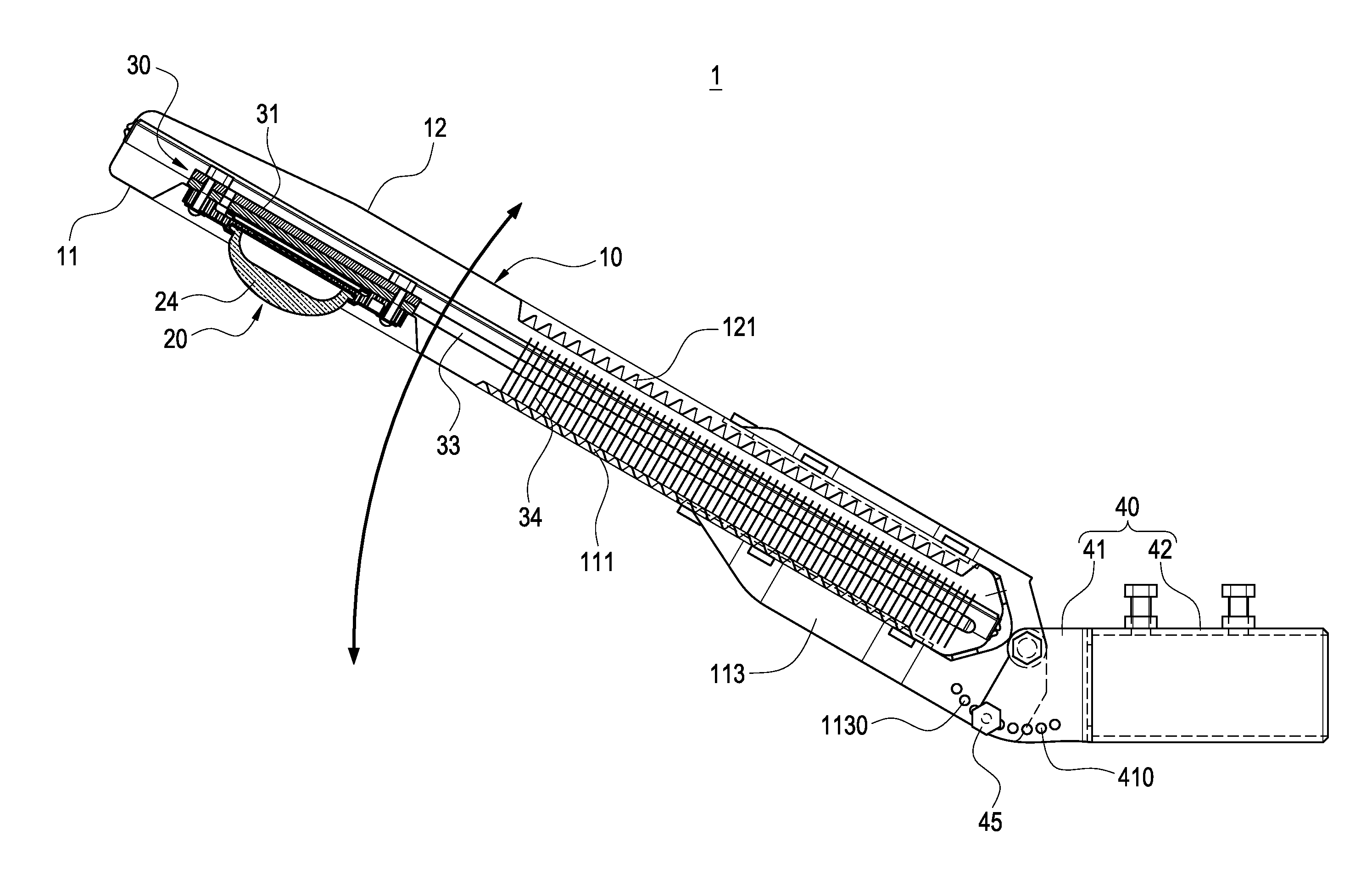
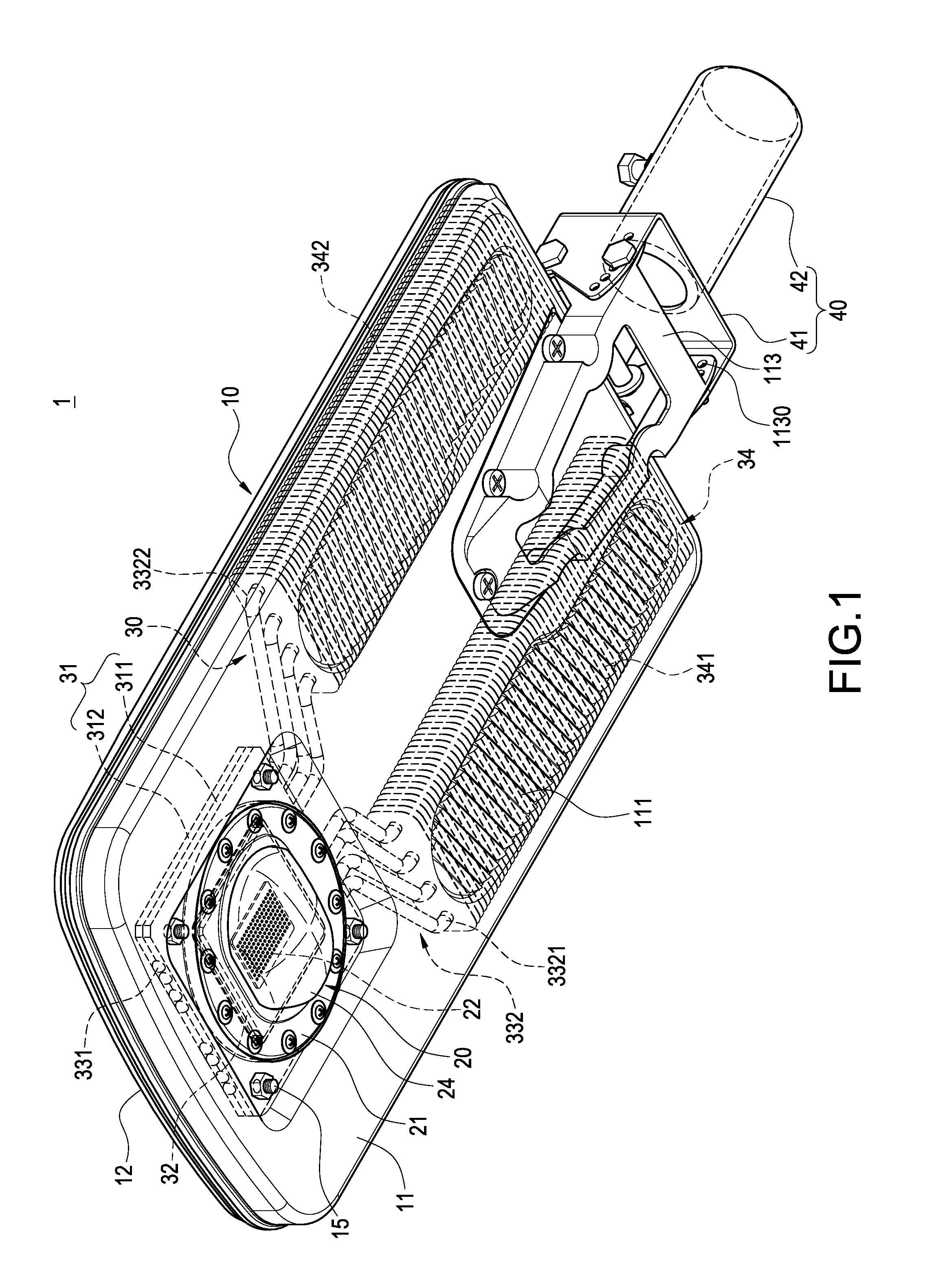
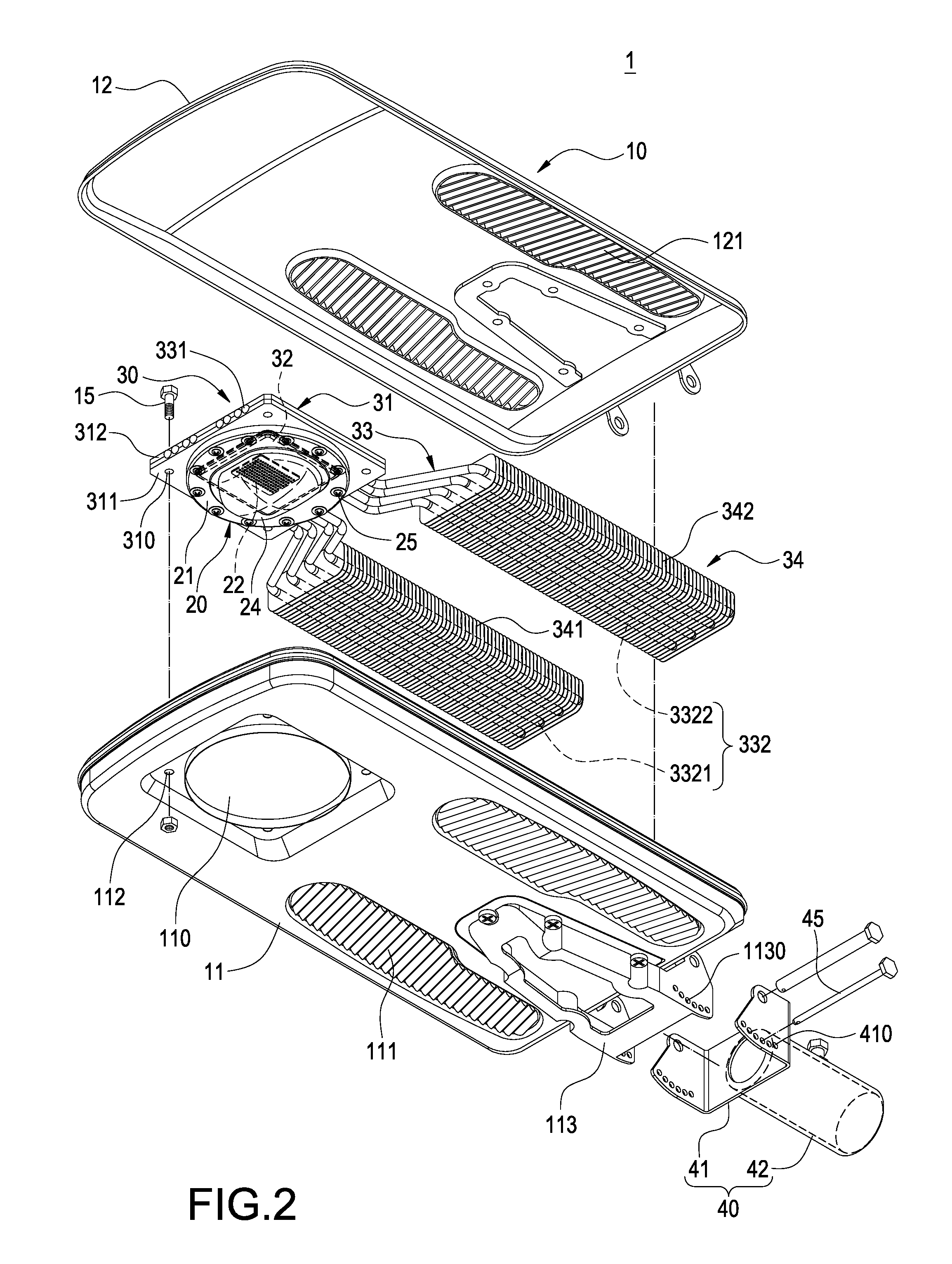
[0022]FIG. 1 to FIG. 4 are respectively a perceptively view, an exploded view, a cross-sectional view and an expanded sectional view of the LED street lamp according to the first embodiment of the present invention. The LED street lamp includes a lamp housing 10, a LED module 20, and a heat dissipating module 30 connected with the LED module 20.

[0023]The lamp housing 10 includes a bottom shell 11 and a top shell 12 accordingly covered on the bottom shell 11. The bottom shell 11 and the top shell 12 cooperatively define an accommodating space 100. The bottom shell 11 is formed with an opening 110 and a plurality of first heat dissipating holes 111 away from the opening 110. The top shell 12 is formed with a plurality of second heat dissipating holes 121 correspon...


PUM


Abstract

A LED street lamp including a housing, a lighting module, a metal base, and a heat dissipating module. The housing includes a bottom shell and a top shell both with openings. The lighting module is arranged in the housing. The heat dissipating module includes a metal base, a plurality of heat pipes, and a plurality of heat dissipating fins. The metal base includes a first plate and a second plate attached together. The first plate is thermally contacted with the lighting module. The heat pipes each have a heat absorbing section and a heat dissipating section. The heat absorbing section is arranged between the first plate and the second plate. The heat dissipating section is extending away from a side of the metal base. The heat dissipating fins are arranged on the heat dissipating sections. Air in the housing can naturally flow upwardly to effectively dissipate operating heat.

Description

BACKGROUND OF THE INVENTION[0001]1. Field of the Invention[0002]The present invention relates to a lighting apparatus, particularly to a LED street lamp.[0003]2. Description of Related Art[0004]Since the operating heat generated from the light emitting diode (LED) has a negative affection to the lifetime of the LED, LED light sources such as LED street lamps usually have heat dissipating device to help removing the operating heat of the LED. However, with the increasing number of LEDs and the adopting of high-powered LEDs in the LED light source, the amount of the operating heat is increasing rapidly. Therefore, how to improve the dissipating efficiency of the heat dissipating device for the LED light source has become a major issue in this industry.[0005]Conventional LED street lamp has a lamp housing, a plurality of LEDs arranged in the lamp housing, and a heat dissipating device arranged above the LEDs. For example, the hest dissipating device could have a base and a plurality of...

Claims


Application Information

Patent Timeline
Patent Type & Authority Applications(United States)
IPC IPC(8): F21V19/02F21V29/00
CPCF21V15/01F21V21/116F21V29/004F21W2131/103F21V29/76F21V29/006Y02B20/72F21V29/71F21Y2101/02F21V29/717F21Y2115/10
Inventor WANG, CHIN-WEN
Owner WANG CHIN WEN
Why Eureka
Try Eureka