
Stroke sensing device for percussion instruments

a detection device and percussion technology, applied in the direction of musical instruments, electrophonic musical instruments, instruments, etc., can solve the problems of detection of vibrations of striking members, and achieve the effects of convenient bending in conformance, efficient transmission, and more reliably detection

Active Publication Date: 2012-01-05
ROLAND CORP
View PDF2 Cites 11 Cited by
  • Summary
  • Abstract
  • Description
  • Claims
  • Application Information

AI Technical Summary

Benefits of technology

[0007]Embodiments of the present invention relate to a percussion instrument striking detection device configured to reduce the time from when a head is struck until the vibrations of the head are detected. In those or additional embodiments, a percussion instrument striking detection device is further configured to reliably detect vibrations that are in conformance with the striking force, without regard to the condition of the head.
[0008]A percussion instrument striking detection device according to an embodiment of the present invention is provided with a shaft member and a striking member. The shaft member is formed in a shaft shape. The striking member has a hollow interior and is attached to one end of the shaft member. In addition, the striking member is provided with a vibration sensor that detects vibrations. As a result, vibrations of the striking member that are produced at the time that the head of the percussion instrument is struck can be detected by the vibration sensor that is inside of the striking member. Therefore, it is possible to make the distance between the vibration sensor and the striking location on the head by the striking member to be relatively short. Accordingly, the time period from when the head is struck to the detection of the vibrations by the vibration sensor can be made relatively short, compared to the case in which the head vibrations are detected at a peripheral portion of the head, distant from the striking location. As a result, the time period from the striking of the head until the generation of the musical tone is minimized and a more realistic and comfortable feeling can be experienced by the performer. In addition, because the vibration sensor detects vibrations of the striking member, it is possible to prevent the occurrence of variations in the detected vibrations in the event that the location at which the head is struck changes because the installed position of the foot pedal has shifted.
[0009]In addition, because the vibration sensor detects vibrations of the striking member that strikes the head, it is possible to suppress the effects of the tension and material of the head on the vibrations that the vibration sensor detects. Therefore, vibrations can be reliably detected in conformance with the striking force. In addition, the vibration sensor is attached to the striking member, which can be configured to have a much smaller surface area compared to the head. Accordingly, it is possible to minimize or avoid vibrations of the striking member due to musical tones that are produced by other musical instruments. Therefore, unwanted detection by the vibration sensor of those striking member vibrations can be suppressed. In addition, vibrations of the striking member can be detected, even in cases where the head is configured by a material such as rubber and the like. Therefore, percussion instrument striking detection devices according to various embodiments of the present invention can be configured for versatility and use in a broad variety of applications.

Problems solved by technology

In addition, vibrations of the striking member can be detected, even in cases where the head is configured by a material such as rubber and the like.

Method used


Image

  • Stroke sensing device for percussion instruments
  • Stroke sensing device for percussion instruments
  • Stroke sensing device for percussion instruments

Examples


Embodiment Construction

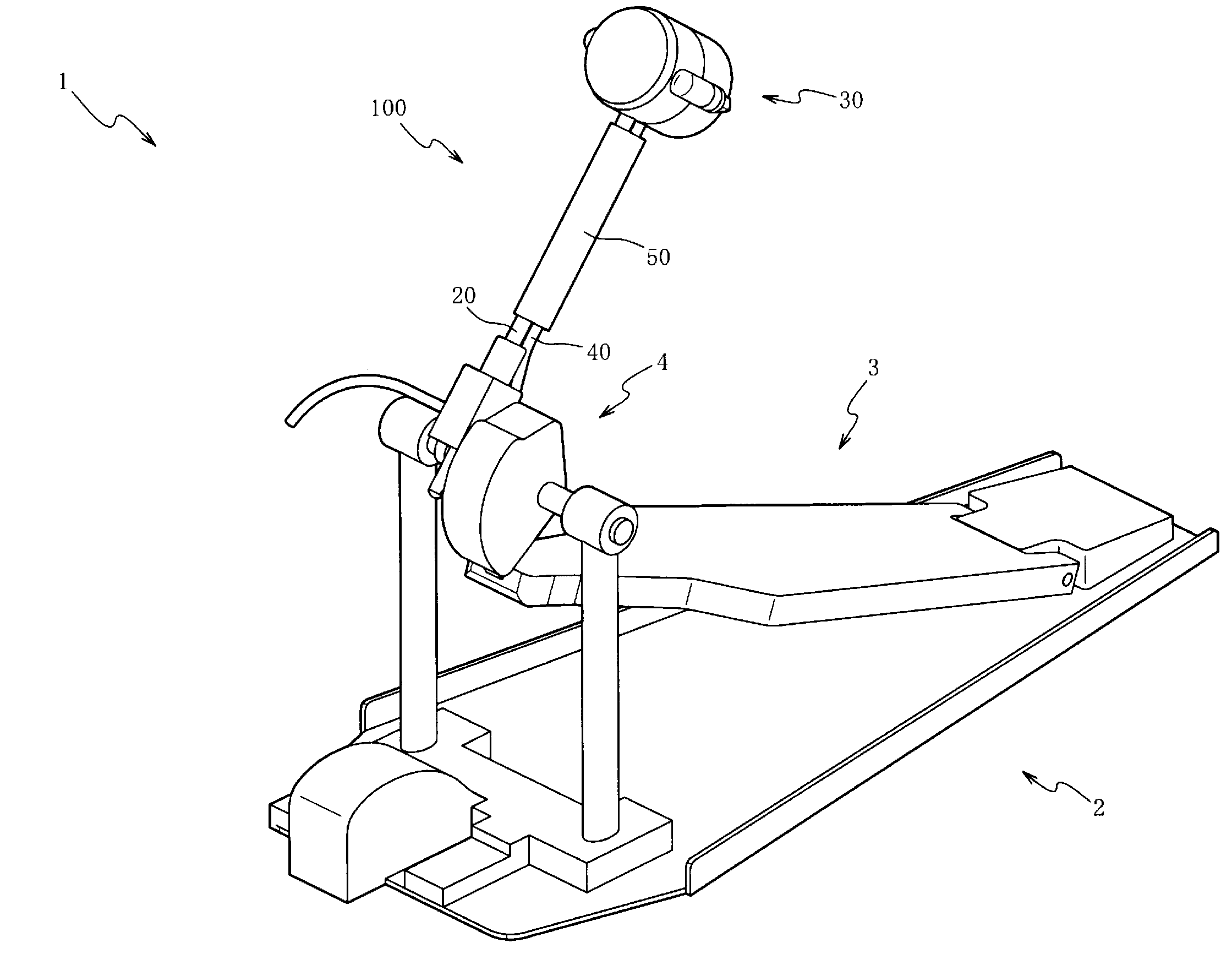
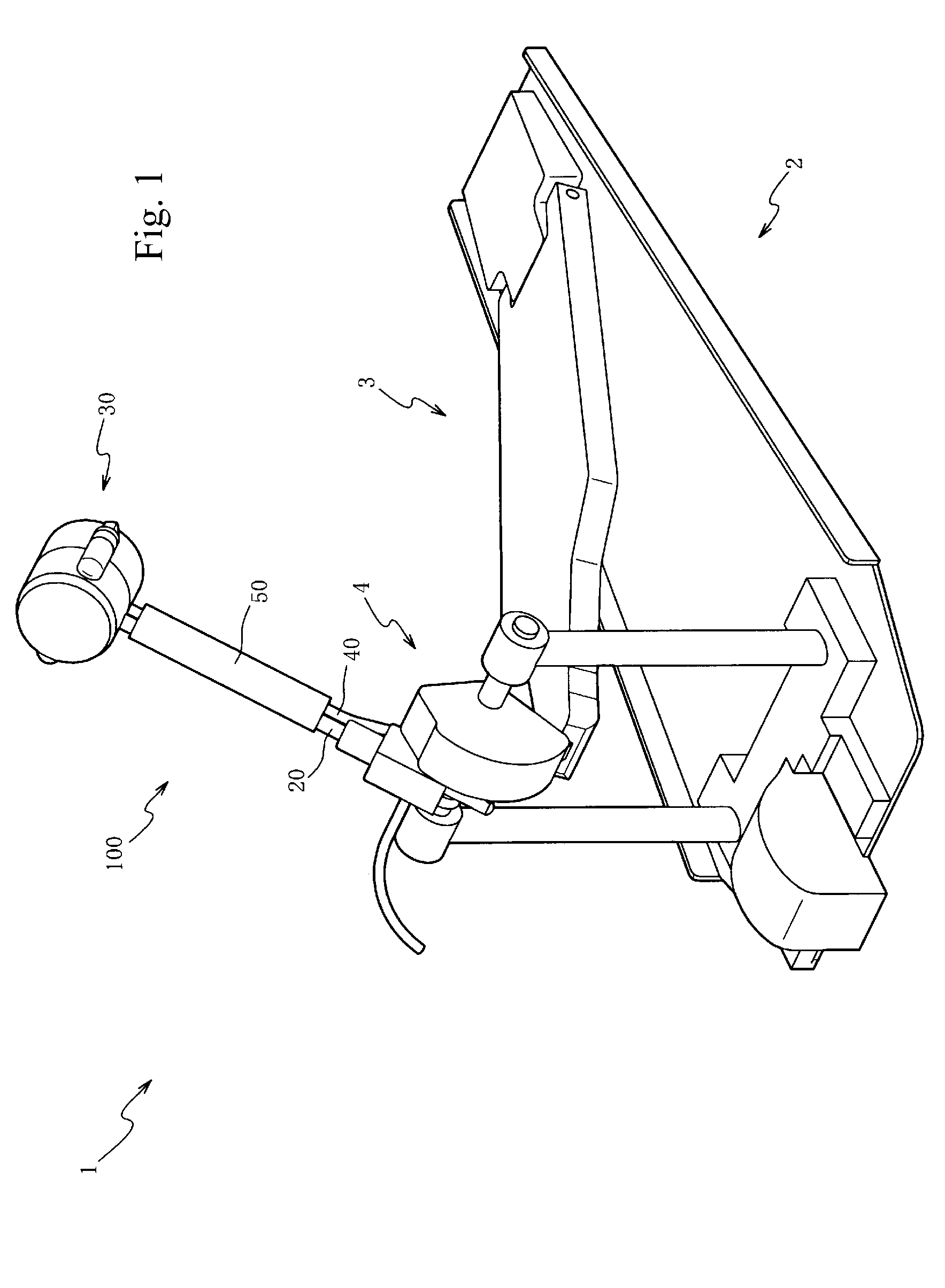
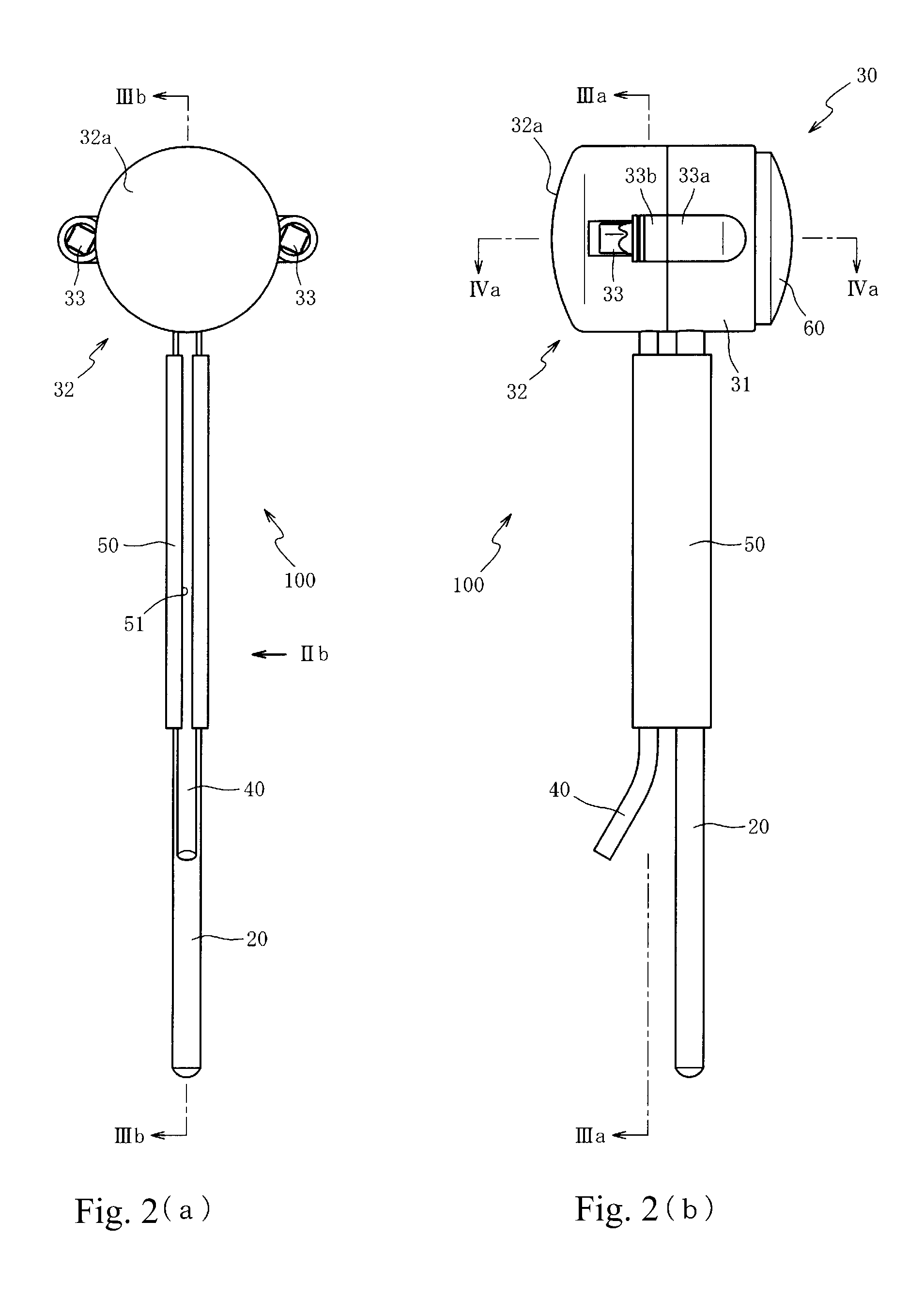
[0031]An explanation will be given below regarding example embodiments of the present invention while referring to the attached drawings. First, an explanation will be given regarding the configuration of the beater 100 while referring to FIG. 1 and FIG. 2. FIG. 1 is a perspective view drawing of a foot pedal on which the beater 100 of a first embodiment of the present invention has been mounted. FIG. 2(a) is a rear view drawing of the beater 100 and FIG. 2(b) is a side view drawing of the beater 100. The foot pedal in FIG. 1 further includes a mechanism (a spring or the like) for returning the foot board 3 to the original position after it has been stepped on, but that mechanism is not shown, to simplify the drawing.

[0032]The foot pedal 1 in FIG. 1 may be arranged to strike the head (not shown in the drawing) of a bass drum (not shown in the drawing), at the time of a performance of the bass drum, in conformance with the treading of the foot of the performer on the foot pedal 1. Th...


PUM


Abstract

A percussion instrument striking detection device is configured to minimize time lag from striking the head until detection of head vibrations and for reliable detection of the vibrations in conformance with the striking force without regard to the head condition. A striking member has a vibration sensor. Therefore, the distance from the striking location on the head to the vibration sensor can be short, to minimize time lag. In addition, the effect of the tension or the material of the head on the vibrations detected by the vibration sensor can be minimized and vibrations in conformance with the striking force can be reliably detected.

Description

CROSS-REFERENCE TO RELATED PATENT APPLICATIONS[0001]Japan Priority Application 2010-151263, filed Jul. 1, 2010 including the specification, drawings, claims and abstract, is incorporated herein by reference in its entirety.BACKGROUND OF THE INVENTION[0002]The present invention relates to a percussion instrument striking detection device and, in particular embodiments, to a percussion instrument striking detection device configured to reduce the time from when a head is struck until the vibrations of the head are detected. In those or additional embodiments, a percussion instrument striking detection device is further configured to reliably detect vibrations that are in conformance with the striking force, without regard to the condition of the head.PRIOR ART[0003]For some time, methods have been known to amplify the musical tone that is generated by the performance of an acoustic drum, where such known methods increase the sound volume or convert the timbre of the musical tone into ...

Claims


Application Information

Patent Timeline
IPC IPC(8): G10D13/02
CPCG10D13/006G10H1/348G10H2230/291G10H3/146G10H2220/525G10H3/143G10D13/11
Inventor MORI, YOSHIAKI
Owner ROLAND CORP
Learn More