Integrated Radio Frequency Front-end Circuit

a radio frequency front-end circuit and integrated technology, applied in amplifiers, electrical devices, semiconductor devices/discharge tubes, etc., can solve the problems of many internal or external components, complex methods, and insufficient characterization of on-chip radio frequency (rf) transformer components, so as to reduce chip area (real estate), reduce energy dissipation, and reduce signal loss

Active Publication Date: 2011-12-29
LTIMINDTREE LTD
View PDF11 Cites 18 Cited by
  • Summary
  • Abstract
  • Description
  • Claims
  • Application Information

AI Technical Summary

Benefits of technology

[0008]The integrated radio frequency (RF) front-end circuit disclosed herein addresses the above stated need for a compact radio frequency (RF) front-end with reduced chip area (real estate), reduced energy dissipation, reduced signal loss, reduced switching loss, and reduced cost of manufacture.

Problems solved by technology

Conventionally, both these methods are complex and require many internal or external components.
However the on-chip radio frequency (RF) transformer component is not available in many foundries.
Furthermore, the on-chip radio frequency (RF) transformer component is not well characterized and induces several signal losses upon implementation.

Method used


Image

  • Integrated Radio Frequency Front-end Circuit
  • Integrated Radio Frequency Front-end Circuit
  • Integrated Radio Frequency Front-end Circuit

Examples


Embodiment Construction

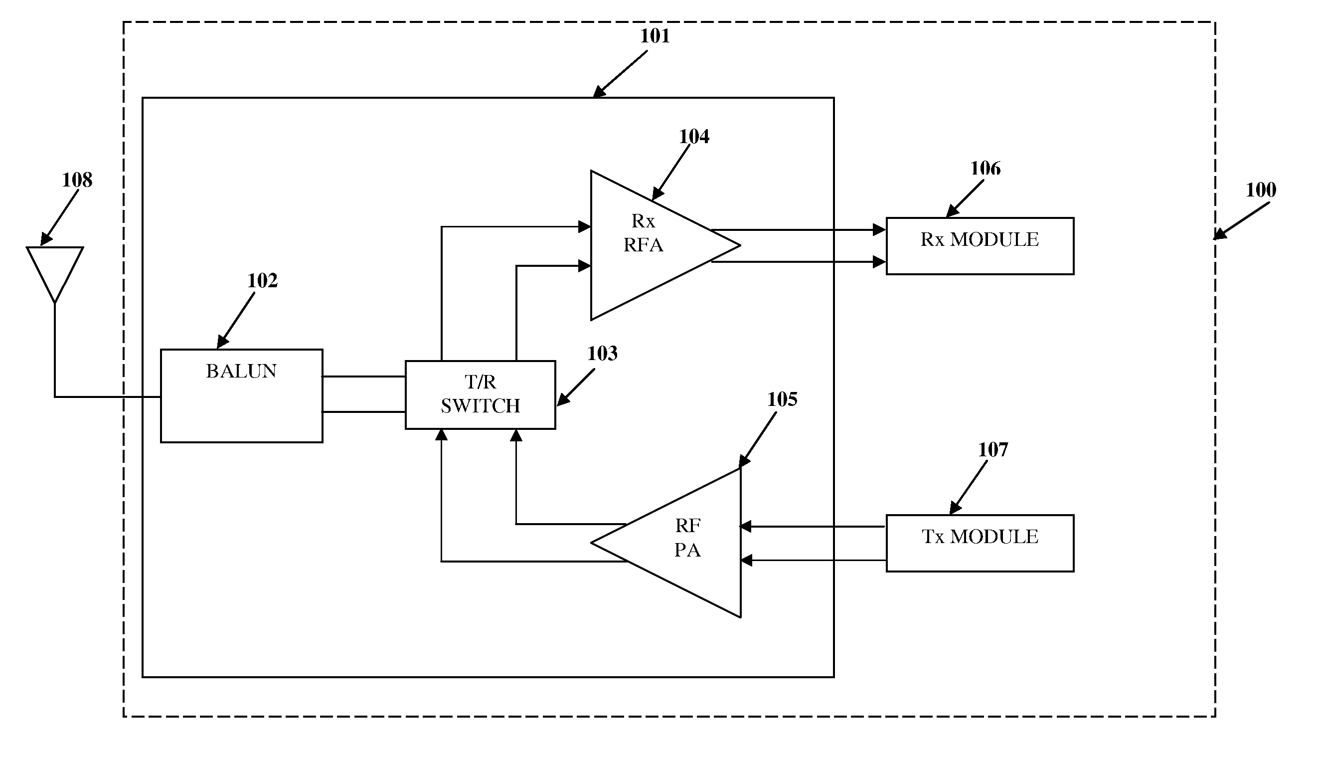
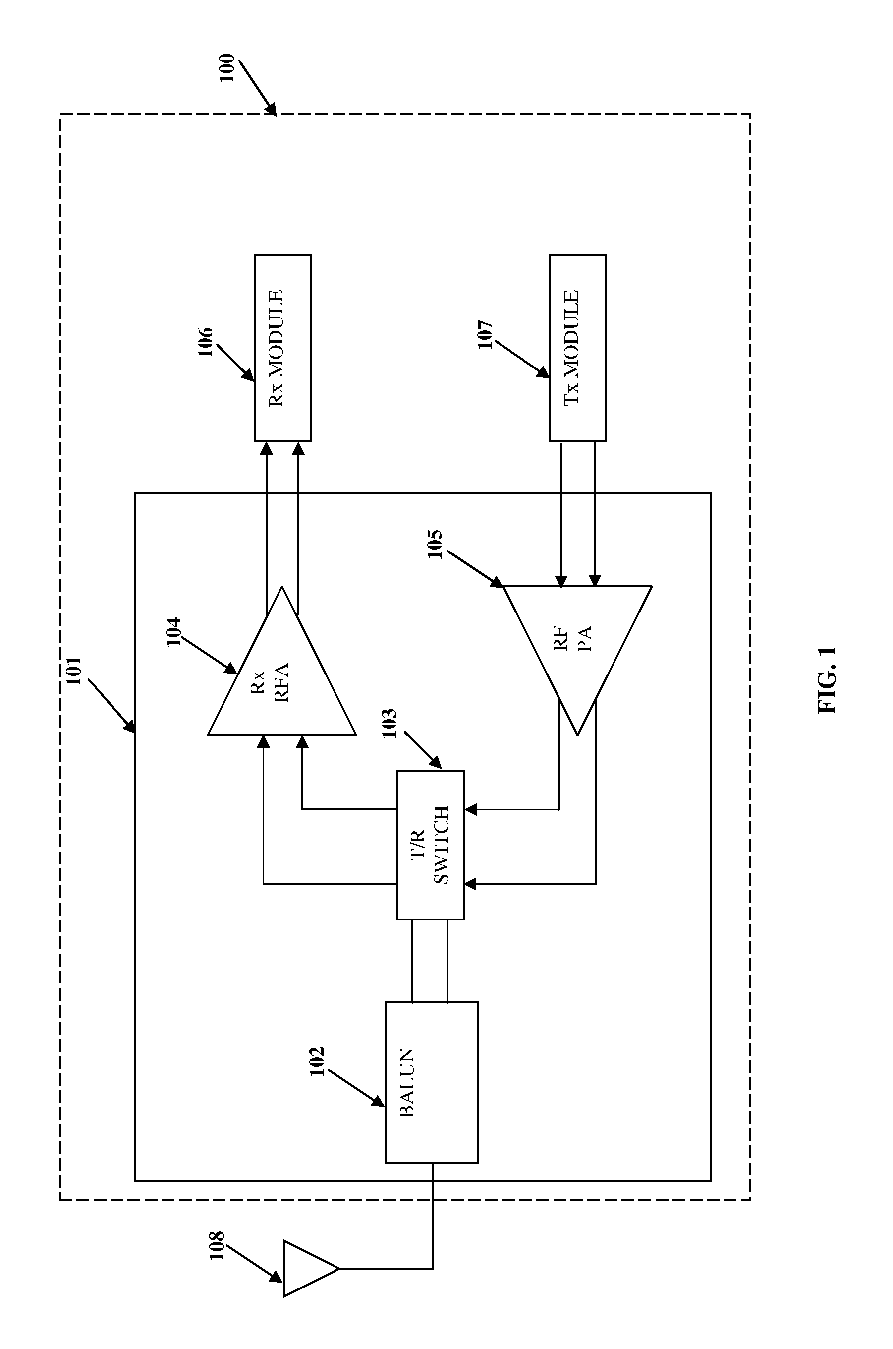
[0024]FIG. 1 illustrates a block diagram of a front-end 101 of a radio frequency (RF) transceiver 100 having a transmit and receive (T / R) switch 103. The radio frequency (RF) transceiver 100 is used to implement two-way radio communication and may be incorporated in wireless radio communication devices. The radio frequency (RF) transceiver 100 comprises an antenna 108, a balun (balanced / unbalanced) 102, the transmit and receive (T / R) switch 103, a receiver radio frequency amplifier (Rx RFA) 104, a radio frequency power amplifier (RFPA) 105, a receiver (Rx) module 106, and a transmitter (Tx) module 107. The balun 102, the transmit and receive (T / R) switch 103, the receiver radio frequency amplifier (Rx RFA) 104, and the radio frequency power amplifier (RFPA) 105 form the radio frequency (RF) front-end 101, where the receiver radio frequency amplifier (Rx RFA) 104 is for example, a low noise amplifier (LNA). The antenna 108 receives an incoming single-ended radio frequency (RF) signal...


PUM


Abstract

An integrated RF front-end circuit comprising a balun, a receiver amplifier, a power amplifier, and a selector circuit is provided. The balun comprises a center-tapped inductor having a first node, a center-tap switchlessly coupled to a fixed voltage, and a second node. The balun receives a single-ended signal through the first node to produce a differential signal at the first and second nodes. The differential signal is provided to balanced input lines of the receiver amplifier. Balanced output lines of the power amplifier provide a differential signal to the first and second nodes. The balun converts the differential signal to a single-ended signal. The single-ended signal is available at the first node of the center-tapped inductor. The selector circuit activates the receiver amplifier and deactivates the power amplifier, and vice versa. The power amplifier may comprise only a single-ended output line connected to either the first or the second node.

Description

CROSS REFERENCE TO RELATED APPLICATIONS[0001]This application claims the benefit of non-provisional patent application number 1752 / CHE / 2010 titled “Integrated Radio Frequency Front-End Circuit”, filed on Jun. 23, 2010 in the Indian Patent Office.[0002]The specification of the above referenced patent application is incorporated herein by reference in its entirety.BACKGROUND[0003]Short range wireless systems utilizing radio frequency (RF) integrated circuits use time division multiplexing for transmitting and receiving signals. The transmitted signals and the received signals use the same frequency band. However, the transmitting (Tx) and receiving (Rx) paths often use differential signaling after a certain stage for increasing performance. The short range wireless systems use a single antenna for both transmission (Tx) and reception (Rx) of signals by utilizing a transmit and receive (T / R) switch. The transmit and receive (T / R) switch toggles the antenna between transmission (Tx) and...

Claims


Application Information

Patent Timeline
Patent Type & Authority Applications(United States)
IPC IPC(8): H04B1/16
CPCH04B1/18H03F3/45188H04B1/40
Inventor SOMAN, MANOJ SHRIDHAR
Owner LTIMINDTREE LTD
Why Eureka
Try Eureka