
Method for encoding signal, and method for decoding signal

Active Publication Date: 2011-12-22
HUAWEI TECH CO LTD
View PDF7 Cites 3 Cited by
  • Summary
  • Abstract
  • Description
  • Claims
  • Application Information

AI Technical Summary

Benefits of technology

[0007]Embodiments of the present disclosure provide a method, apparatus, and system for encoding and decoding signals to improve the compression performance of the codec.
[0043]In the embodiments of the present disclosure, a subsequent encoding or decoding process is performed adaptively according to the long-term flag; when the long-term flag is the second flag, it is not necessary to consider the LTP processing result, thus improving the compression performance of the codec.

Problems solved by technology

Consequently, the pitch gain quantization consumes too many bits, and the compression performance of the coder is reduced.

Method used


Image

  • Method for encoding signal, and method for decoding signal
  • Method for encoding signal, and method for decoding signal
  • Method for encoding signal, and method for decoding signal

Examples


first embodiment

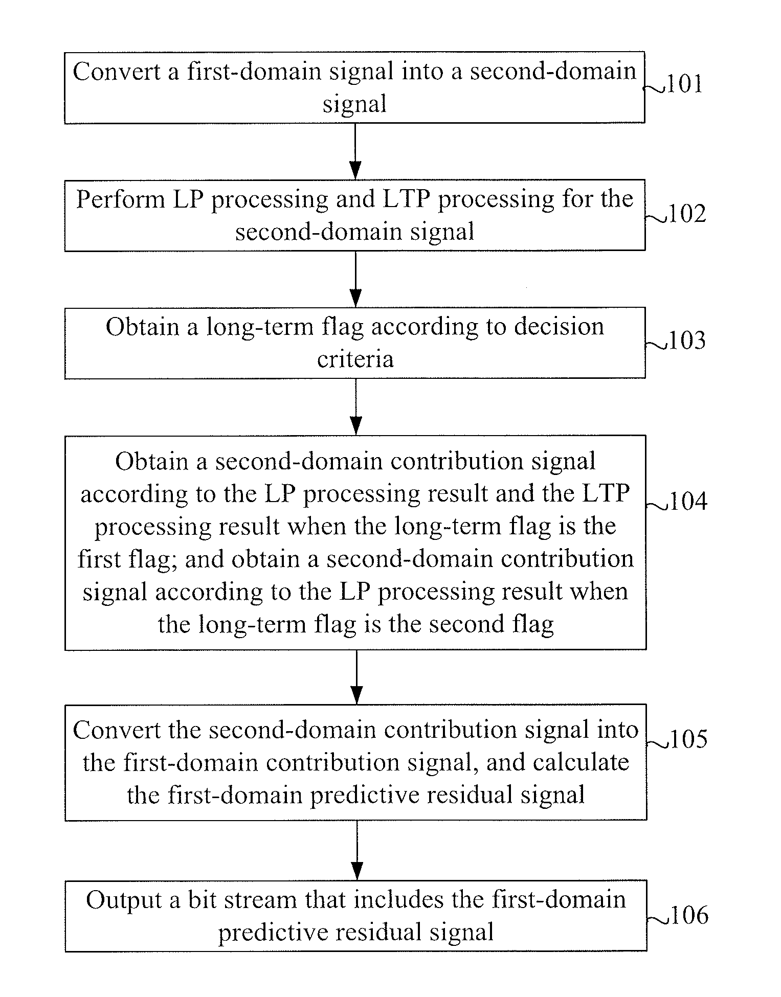
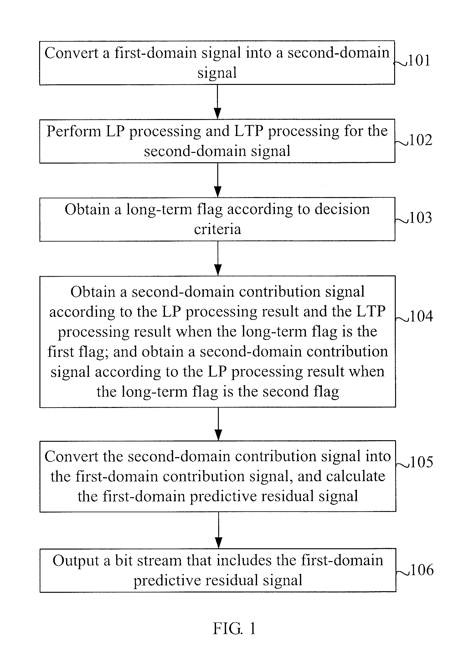
[0055]FIG. 1 is a flowchart of a signal encoding method in the present disclosure. The method includes the following steps:

[0056]Step 101: Convert a first-domain signal into a second-domain signal.

[0057]Step 102: Perform LP processing and LTP processing for the second-domain signal.

[0058]Step 103: Obtain a long-term flag according to decision criteria.

[0059]Step 104: Obtain a second-domain contribution signal according to the LP processing result and the LTP processing result when the long-term flag is the first flag; and obtain a second-domain contribution signal according to the LP processing result when the long-term flag is the second flag.

[0060]Step 105: Convert the second-domain contribution signal into the first-domain contribution signal, and calculate the first-domain predictive residual signal.

[0061]Step 106: Output a bit stream that includes the first-domain predictive residual signal.

[0062]In this embodiment, the long-term flag is obtained according to the decision crite...

second embodiment

[0063]FIG. 2 is a flowchart of a signal encoding method in the present disclosure. In this embodiment, the first domain is a nonlinear domain, and further, the first domain may be A-law or Mu-law; the second domain is a PCM domain; the LP processing is LPC processing, and the LTP processing is Long Term Prediction processing.

[0064]The method in this embodiment includes the following steps:

[0065]Step 201: Convert a nonlinear-domain signal into a PCM-domain signal.

[0066]x(i) represents the nonlinear-domain signal, and y(i) represents the PCM-domain signal. Supposing the conversion process involves precision loss, the corresponding back-conversion process involves no precision loss.

[0067]Step 202: Perform LPC processing for the entire-frame signal y(i) of the PCM domain to obtain an LP processing result. The LP processing result includes the LPC contribution signal y′(i) which serves as an LP contribution signal, and includes an LP coefficient, as expressed in the following formula:

y′(...


PUM


Abstract

The present disclosure relates to a method, apparatus, and system for encoding and decoding signals. The encoding method includes: converting a first-domain signal into a second-domain signal; performing Linear Prediction (LP) processing and Long-Term Prediction (LTP) processing for the second-domain signal; obtaining a long-term flag according to decision criteria; obtaining a second-domain contribution signal according to the LP processing result and the LTP processing result when the long-term flag is a first flag; obtaining a second-domain contribution signal according to the LP processing result when the long-term flag is a second flag; converting the second-domain contribution signal into a first-domain contribution signal, and calculating a first-domain predictive residual signal; and outputting a bit stream that includes the first-domain predictive residual signal. With the present disclosure, a subsequent encoding or decoding process is performed adaptively according to the long-term flag; when the long-term flag is the second flag, it is not necessary to consider the LTP processing result, thus improving the compression performance of a codec.

Description

CROSS-REFERENCE TO RELATED APPLICATIONS[0001]This application is a continuation of International Application No PCT / CN2009 / 076306, filed on Dec. 30, 2009, which claims priority to Chinese Patent Application No. 200810247427.6, filed on Dec. 31, 2008 and Chinese Patent Application No. 200910151835.6, filed on Jun. 25, 2009, all of which are hereby incorporated by reference in their entireties.FIELD OF THE DISCLOSURE[0002]The present disclosure relates to speech encoding and decoding, and in particular, to a method, apparatus, and system for encoding and decoding signals.BACKGROUND OF THE DISCLOSURE[0003]One of the coding models widely applied in the speech coding field is Code Excited Linear Prediction (CELP). The CELP model uses an almost white excitation signal to excite two time-varying linear recursive filters. The excitation signal is generally selected out of a codebook composed of Gaussian white noise sequences. The feedback loop of each filter includes a predictor. One of the...

Claims


Application Information

Patent Timeline
IPC IPC(8): G10L19/00
CPCG10L19/0017H04N19/50G10L19/09G10L19/04G10L19/08H03M7/30
Inventor ZHANG, DEJUNMIAO, LEIXU, JIANFENGQI, FENGYANZHANG, QINGLI, LIXIONGMA, FUWEIGAO, YANG
Owner HUAWEI TECH CO LTD
Learn More