
Device And Method For Processing Light-Polymerizable Material For Building Up An Object In Layers

a technology of light-polymerizable materials and objects, applied in the field of objects building up, can solve the problems of inability to improve, thin layers cannot be applied in reproducible fashion, and methods used today for ceramic dental restoration elements produced by removing materials

Active Publication Date: 2011-12-22
VIENNA UNIVERSITY OF TECHNOLOGY +1
View PDF2 Cites 118 Cited by
  • Summary
  • Abstract
  • Description
  • Claims
  • Application Information

AI Technical Summary

Benefits of technology

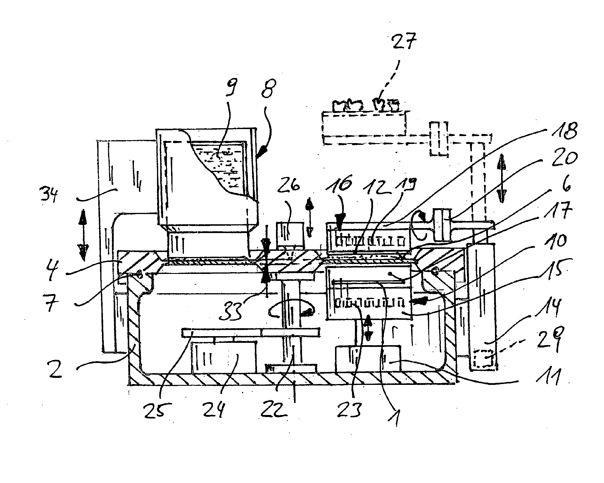
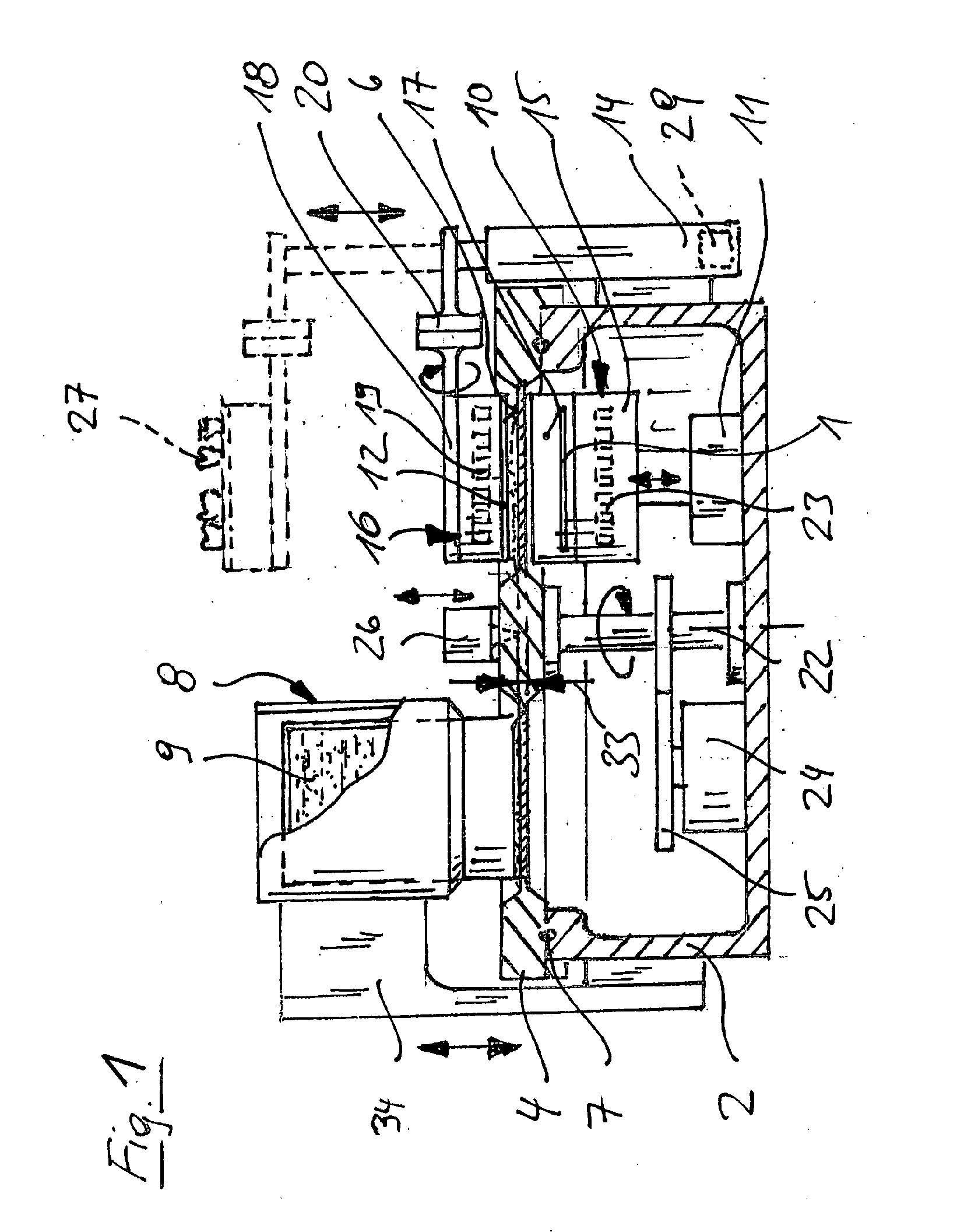
[0013]The invention relates to a device for processing light-polymerizable material for building up an object in layers, using lithography-based generative fabrication, for example rapid prototyping, with a vat with an at least partially transparently or translucently formed horizontal bottom, into which light-polymerizable material can be filled, a horizontal build platform which is held at a settable height above the vat bottom, an exposure unit, which can be controlled for position selective exposure of a surface on the build platform with an intensity pattern with predetermined geometry, a control unit, which is arranged for polymerizing in successive exposure steps layers lying one above the other on the build platform, respectively with predetermined geometry, by controlling the exposure unit and for adjusting, after each exposure step for a layer, the relative position of the build platform to the vat bottom, in order in this way to build up the object successively in the desired form, which results from the sequence of the layer geometries.

Problems solved by technology

However, the methods customary today for producing ceramic dental restoration elements by removing material have several disadvantages, which cannot be improved with reasonable expenditure from economic aspects by the current state of the art.
When using materials of relatively high viscosity, as ceramic-filled resins are, it is only with difficulty, however, that such thin layers can be applied in a reproducible manner.
The small depth of penetration also makes it difficult to achieve reliable bonding of the first layer directly on the build platform.
In the case of ceramic-filled monomer material, however, it cannot be ensured that the initial starting layer is sufficiently thin (for example less than 75 μm).
Consequently, a reproducible bonding force on the build platform could not be ensured even with very long exposure of the first layer.In comparison with unfilled photopolymers, ceramic-filled polymerizable materials are significantly more viscous.
In particular, the time that is required for ceramic-filled photopolymer to flow in after raising of the build platform may be considerably longer.

Method used


Image

  • Device And Method For Processing Light-Polymerizable Material For Building Up An Object In Layers
  • Device And Method For Processing Light-Polymerizable Material For Building Up An Object In Layers
  • Device And Method For Processing Light-Polymerizable Material For Building Up An Object In Layers

Examples


Embodiment Construction

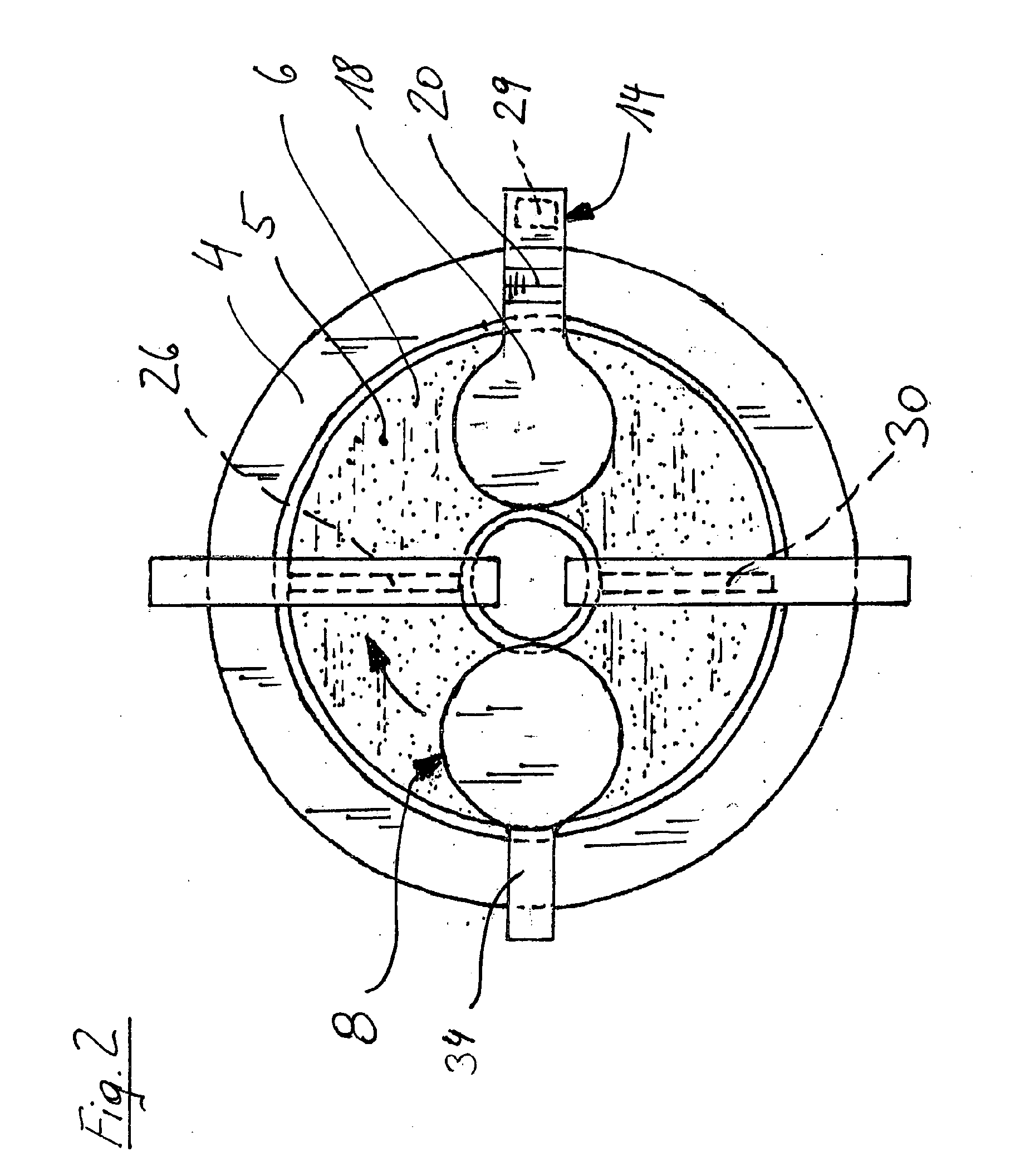
[0022]The device according to the invention is characterized in that the vat is horizontally movable with respect to the exposure unit and the build platform and in that a feed device is provided and, under the control of the control device, discharges light-polymerizable material into the vat, the exposure unit and the build platform being arranged horizontally at a distance from the feed device, and in that the control unit is arranged for moving the vat between successive exposure steps in a prescribed way into a horizontal plane by a drive in order to bring light-polymerizable material that has been discharged in this way by the feed device onto the vat bottom into the region between the exposure unit and the build platform.

[0023]In a preferred embodiment, arranged between the feed device and the exposure unit / build platform in the direction of movement of the vat is an application device, in particular a doctor blade or a roller, the height of which above the vat bottom can be ...


PUM

PropertyMeasurementUnit
thicknessaaaaaaaaaa
thicknessaaaaaaaaaa
thicknessesaaaaaaaaaa

Abstract

A method and a device for processing light-polymerizable material for the assembly of a mold, utilizing a lithography-based generative manufacturing technique wherein a layer of a light-polymerizable material, the material being located in at least one trough (4) having a particularly light-transmissive, horizontal bottom (6), is polymerized by illumination on at least one horizontal platform (12), the platform having a prespecified geometry and projecting into a trough (4), in an illumination field, wherein the platform (12) is displaced vertically to form a subsequent layer, light-polymerizable material is then added to the most recently formed layer, and repetition of the foregoing steps leads to the layered construction of the mold in the desired form, which arises from the succession of layer geometries. The invention is characterized in that the trough (4) can be shifted horizontally to a supply position, and the supply device (8) brings light-polymerizable material at least to an illumination field of the trough bottom (6), before the at least one trough (4) is shifted to an illumination position in which the illumination field is located below the platform (12) and above the illumination unit (10), and illumination is carried out.

Description

CROSS-REFERENCE TO RELATED APPLICATIONS[0001]This application claims the benefit of International Application No. PCT / EP2008 / 008864 (Publication No. WO 2010 / 045950 A1), filed Oct. 20, 2008, which is hereby incorporated by reference in its entirety.TECHNICAL FIELD[0002]The invention is directed at the building up of objects and, in particular, to the building up of objects that are intended to be used for dental restorations.BACKGROUND OF THE INVENTION[0003]CAD-CAM technologies have been established in the dental sector for some time and have taken the place of the traditional manual crafting of tooth replacements. However, the methods customary today for producing ceramic dental restoration elements by removing material have several disadvantages, which cannot be improved with reasonable expenditure from economic aspects by the current state of the art. In this connection, building-up methods of production that are known under the term “rapid prototyping” can be considered, in parti...

Claims


Application Information

Patent Timeline
Patent Type & Authority Applications(United States)
IPC IPC(8): G03B27/42
CPCA61C13/0013B29C67/0051B29C67/0062B29C64/124B33Y10/00B33Y30/00
Inventor ROHNER, GOTTFRIEDWACHTER, WOLFGANGAPPERT, CHRISTOPHPATZER, JOHANNESSTAMPFL, JURGEN
Owner VIENNA UNIVERSITY OF TECHNOLOGY
Learn More