
Composite anisotropic tissue reinforcing implants having alignment markers and methods of manufacturing same

Active Publication Date: 2011-12-15
ETHICON INC
View PDF6 Cites 60 Cited by
  • Summary
  • Abstract
  • Description
  • Claims
  • Application Information

AI Technical Summary

Benefits of technology

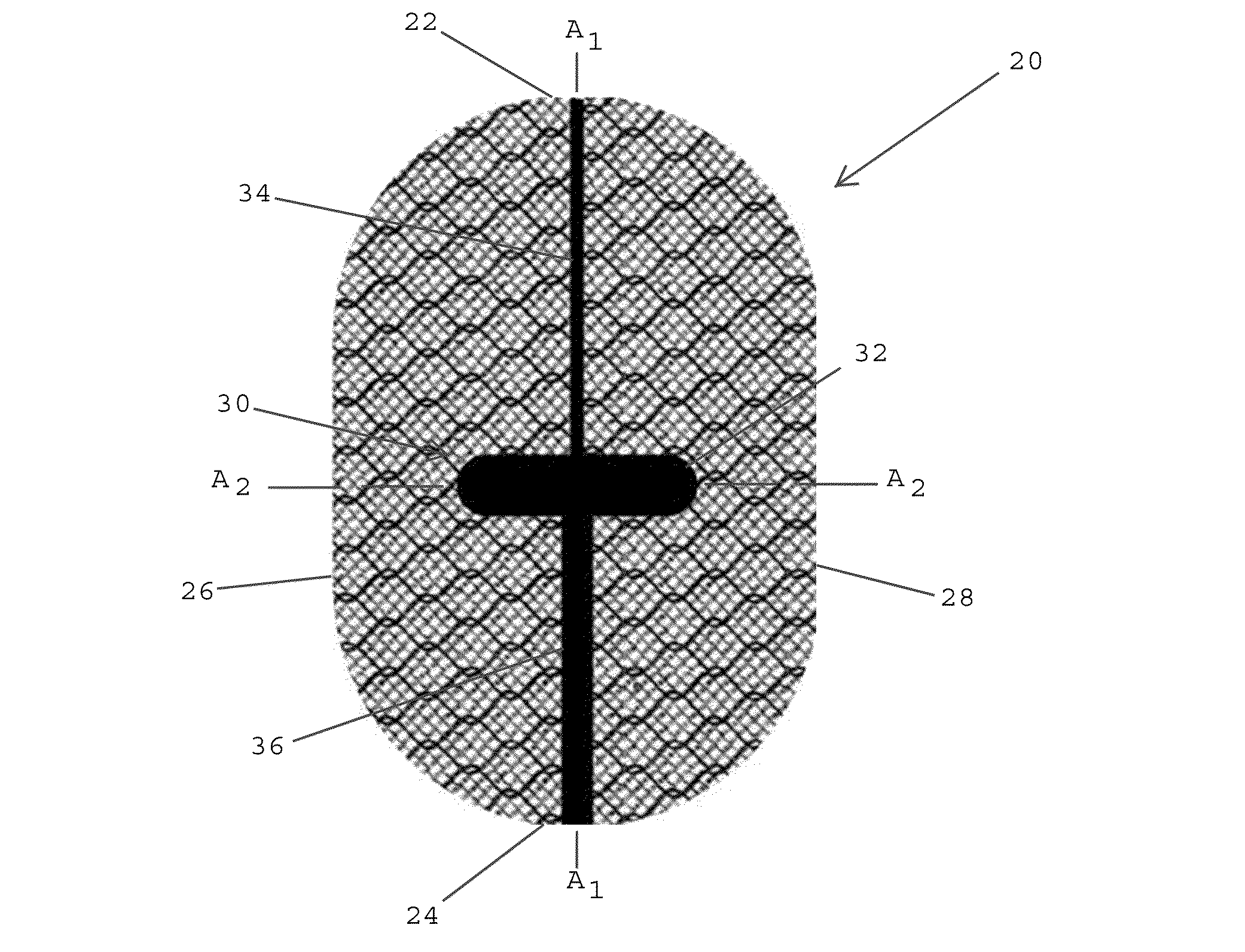
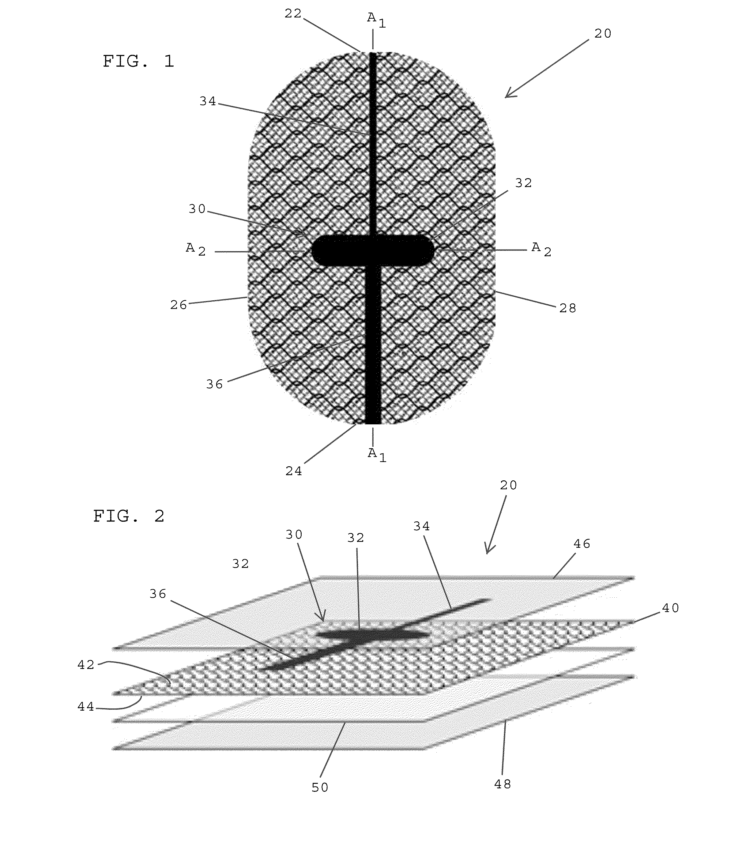
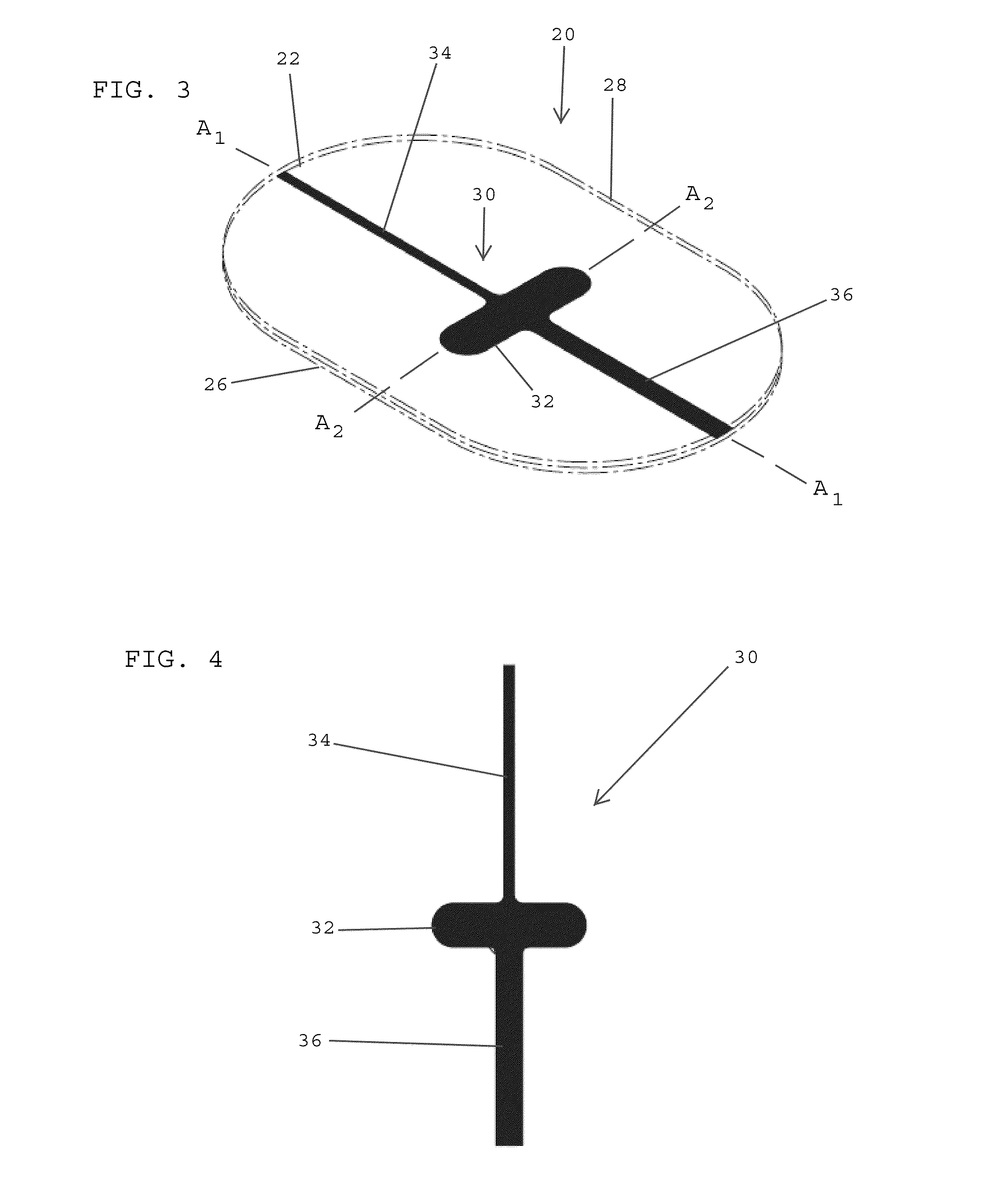
[0013]In one embodiment, the alignment marker is asymmetric and is desirably adapted to clearly show the center of the implant and the preferred placement direction for the implant. In one embodiment, the asymmetric alignment marker preferably includes two different marking lines running from a center region of the marker. The two marking lines preferably have different widths indicating the anisotropic elongation behavior of the surgical mesh. Outside the alignment marker region, the implant device is preferably transparent thereby allowing surgical personnel to see through the implant and observe critical structures such as underlying tissue, nerves and / or vessels.
[0016]In one embodiment, the tissue reinforcing film desirably includes a surgical mesh having pores extending between the first and second major surfaces thereof. In one embodiment, the surgical mesh preferably includes an anisotropic material adapted to have more stretch along a first axis and less stretch along a second axis that traverses the first axis. In one embodiment, the alignment marker desirably extends along the first axis of the implant for indicating the direction of the implant having more stretchability.
[0027]In one embodiment, the composite implant is preferably adapted to be folded for passing the implant through a trocar and then unfolded after passing from a distal end of the trocar. In one embodiment, prior to insertion through the trocar, the composite implant is preferably rolled up so that the marking lines of the alignment marker form the mid-axis of the implant. In one embodiment, the composite implant may be inserted through a trocar, and after deployment of the implant, the alignment marker including the marking lines are used for aligning the implant. In one embodiment, upon deployment of the implant, the marking lines preferably run from cranial to caudal. As such, after absorption of the absorbable films, there is a strained behavior in the implant in the desired orientation. As a result, the difficult process of intra-operative unfolding the implant with rotation by 90 degrees is avoided.

Problems solved by technology

There are a number of problems associated with convention implants.

Method used


Image

  • Composite anisotropic tissue reinforcing implants having alignment markers and methods of manufacturing same
  • Composite anisotropic tissue reinforcing implants having alignment markers and methods of manufacturing same
  • Composite anisotropic tissue reinforcing implants having alignment markers and methods of manufacturing same

Examples


Embodiment Construction

[0044]Referring to FIG. 1, in one embodiment, a composite tissue reinforcing implant 20 preferably includes a first end 22, a second end 24, a first lateral side 26, and a second lateral side 28. The tissue reinforcing implant 20 desirably has an alignment marker 30 including a central region 32 that preferably indicates a center of the implant 20, a first marking line 34 that extends from the central region 32 of the alignment marker to the first end 22 of the implant 20, and a second marking line 36 that extends between the central region 32 of the alignment marker and the second end 24 of the implant 20. In one embodiment, the alignment marker preferably assists medical personnel in properly orienting and aligning the composite implant 20 over a patient's tissue so as to match the anisotropic properties of the implant with the anisotropic properties of the tissue.

[0045]Referring to FIGS. 1 and 2, in one embodiment, the tissue reinforcing implant is preferably a composite implant ...


PUM

PropertyMeasurementUnit
Temperatureaaaaaaaaaa
Forceaaaaaaaaaa
Pressureaaaaaaaaaa

Abstract

A composite implant includes an anisotropic surgical mesh having more stretchability along a first axis and less stretchability along a second axis that traverses the first axis, and an alignment marker overlying a first major surface of the anisotropic mesh and extending along the first axis. The implant includes a first absorbable, anti-adhesion film overlying the alignment marker and the first major surface of the anisotropic mesh, and a second absorbable, anti-adhesion film overlying the second major surface of the biocompatible mesh. The alignment marker is disposed between the first and second absorbable films and the first and second absorbable films are laminated to the anisotropic mesh.

Description

CROSS-REFERENCE TO RELATED APPLICATIONS[0001]The present application is related to commonly assigned U.S. Design patent application Ser. No. 29 / 363,759, filed on even date herewith, the disclosure of which is hereby incorporated by reference herein.BACKGROUND OF THE INVENTION[0002]1. Field of the Invention[0003]The present invention generally relates to medical implants, and more specifically relates to tissue reinforcing implants.[0004]2. Description of the Related Art[0005]The use of tissue reinforcing implants, such as polymer meshes, is widespread. In 1995, a procedure was developed by F. Ugahary that combines the advantages of pre-peritoneal mesh fixation with the convenience of using small incisions for forming access openings.[0006]Laparoscopic techniques have been developed for repairing inguinal hernias. One technique uses a trans-abdominal pre-peritoneal mesh-plasty (TAPP), whereby an implant mesh is preperitoneally positioned through a trans-abdominal laparoscopic access ...

Claims


Application Information

Patent Timeline
IPC IPC(8): A61F2/02B32B38/08
CPCA61F2/0045A61F2/0063A61F2250/0097A61F2250/0067A61F2250/0031
Inventor PFEIFFER, RUTHPRIEWE, J+E,UML O+EE RGSCHULDT-HEMPE, BARBARAWALTHER, CHRISTOPH
Owner ETHICON INC
Learn More