
Transverse flux, switched reluctance, traction motor with bobbin wound coil, with integral liquid cooling loop

a traction motor and switched reluctance technology, applied in the motor field, can solve the problems of high assembly cost, low power efficiency, and difficult assembly process, and achieve the effects of reducing assembly cost, reducing assembly cost, and increasing torqu

Inactive Publication Date: 2008-07-31
ARVINMERITOR TECH
View PDF7 Cites 35 Cited by
  • Summary
  • Abstract
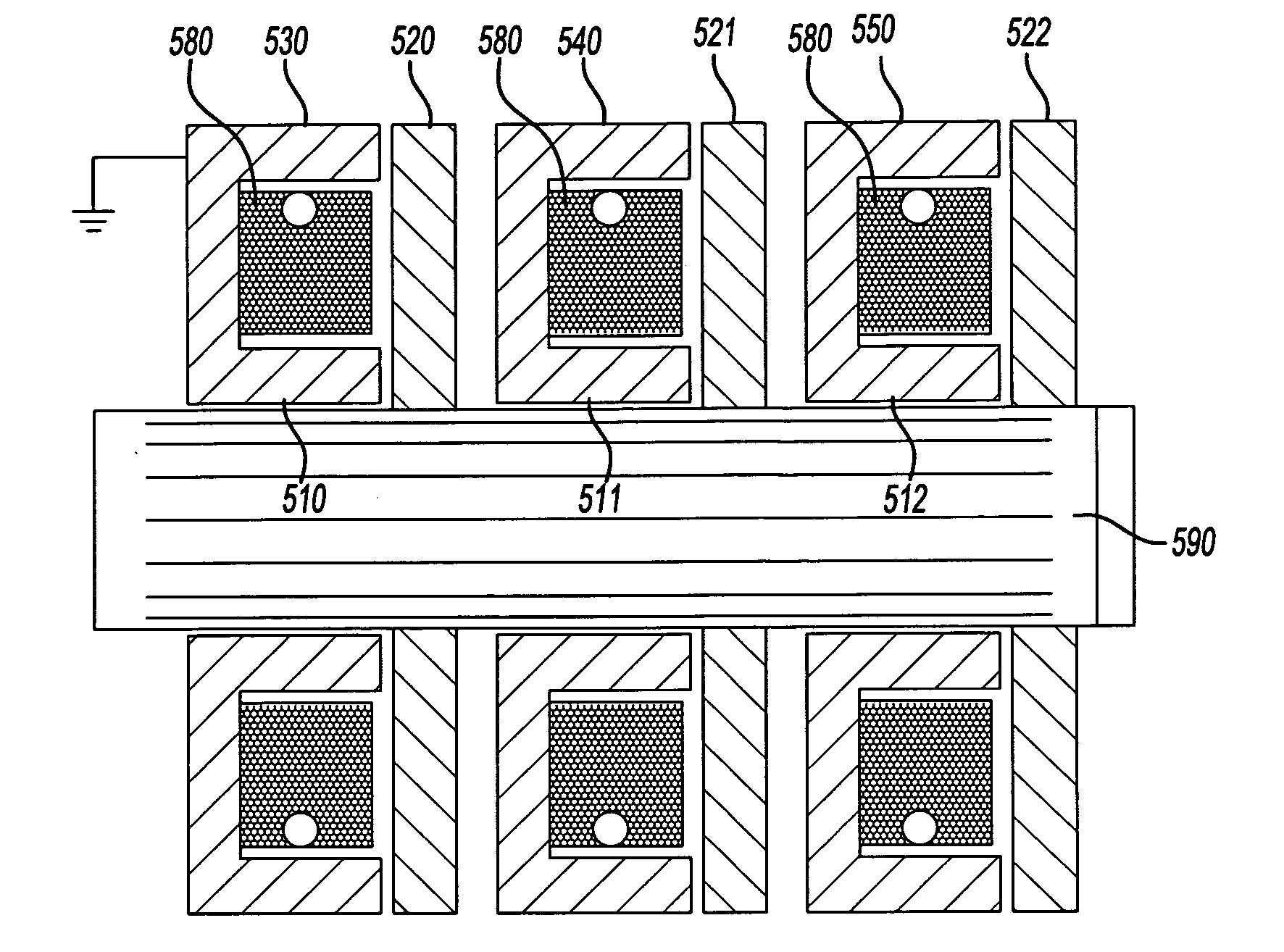
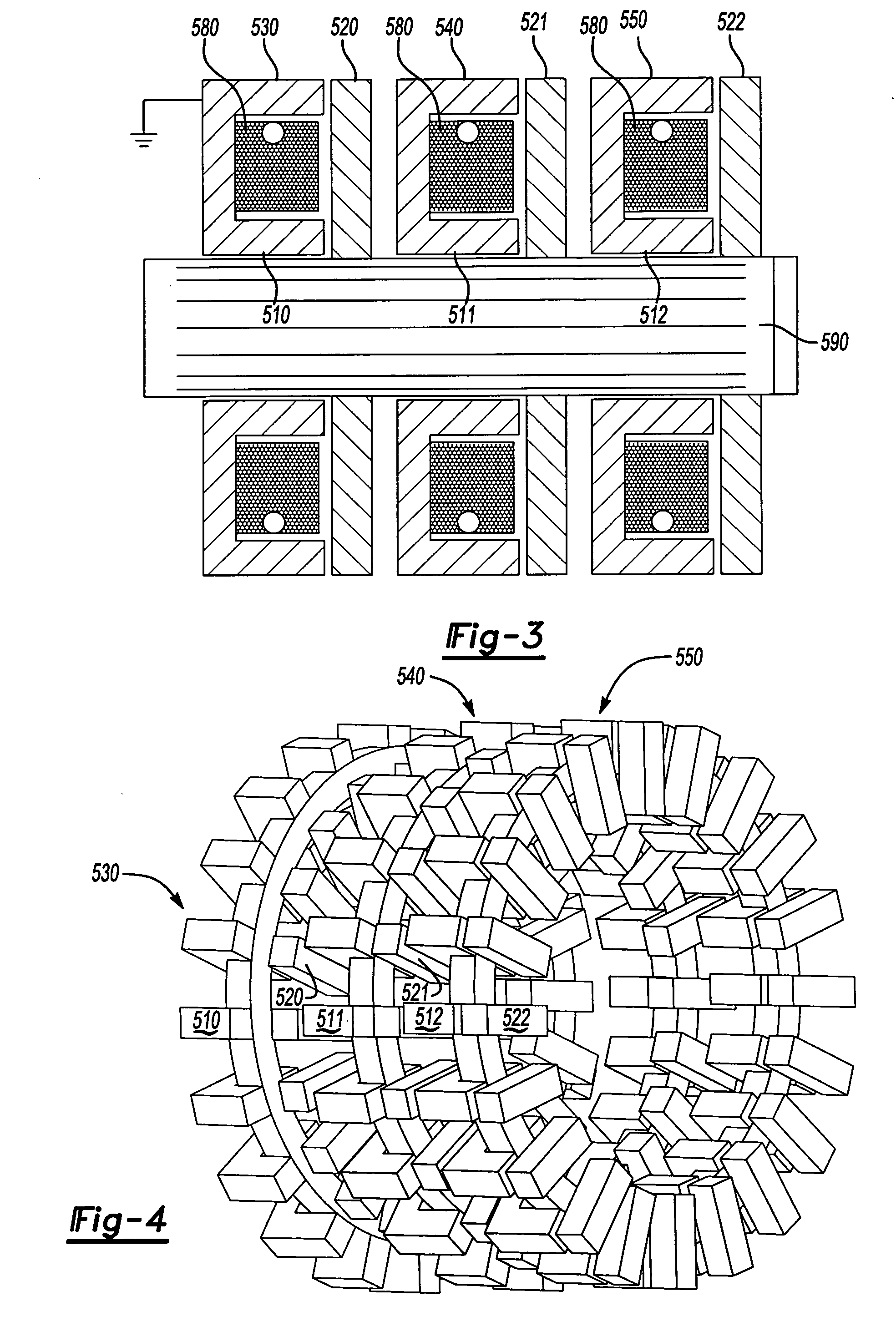
  • Description
  • Claims
  • Application Information

AI Technical Summary

Benefits of technology

[0006]The goal of the current invention is to design a switched reluctance transverse flux machine that is lighter in weight and produces higher torque. Additionally the goal of the present invention is to reduce assembly costs, and reduce the space required for the machine.
[0007]The invention relates to an axially spaced, transverse flux, switched reluctance, traction motor utilizing a single simple wound bobbin coil for each phase winding. As a separate inventive feature, an integral cooling loop is built into each phase winding. Transverse flux, switched reluctance machines are known in the art and provide a variety of benefits including simple design and an acceptable power to weight ratio. Some downsides of using switched reluctance machines are that they have a difficult assembly processes, do not have as high a power efficiency as permanent magnet transverse flux machines, and have high assembly costs.
[0008]It is known in the art to create a switched reluctance machine by spacing the phases radially around the rotor. The present invention spaces the phases axially along the rotor. Axial spacing allows the switched reluctance machine to be arranged in such a way that the machine can be constructed using a modular construction technique. The modular construction technique allows each phase to be assembled individually and then be “snapped” together with the other phases. Additional construction techniques not using modular assembly are possible with axially spaced phases, all of which are easier than the assembly techniques of the prior art switched reluctance machines.
[0009]A feature of the phase winding construction is made possible by the axial spacing and contributes to the ease in assembly. Known switched reluctance machines, as well as permanent magnet systems, use ‘daisy chained’ windings, or even more complex and intricate coil winding arrangements. The axial spaced windings with only one coil per phase allows a simple wound bobbin coil to be used for the windings. In this case the windings are circular and easy to assemble. This simple wound bobbin coil not only aids in ease of assembly but uses less copper wire, and reduces the overall weight of the switched reluctance machine. A third benefit resulting from the simple wound bobbin coils is the possibility of adding an integrated cooling loop within the electrical windings.
[0010]An integrated cooling loop is a hollow loop wound around the bobbin and embedded within the coil. The loop can be constructed of any material capable of being formed into a tube, having good heat transfer characteristics, and being capable of containing a refrigerant gas or liquid without leakage. The material would also provide benefits if non-conductive to electricity. The embedded cooling loop allows a refrigerant to be pumped through the coil while the switched reluctance machine is in operation. While the refrigerant is pumped through the coils heat is transferred from the coils to the refrigerant, thus cooling the overall system. The hot refrigerant then flows outside the coils. Once outside the coils, the refrigerant is cooled via a heat exchanger and pumped back through the embedded cooling loop. This allows temperature regulation within the coils themselves, providing for higher efficiency and a higher torque output. It is also envisioned that a similar effect could be accomplished using hollow wires to create the winding and pumping the cooling refrigerant directly through the winding wires themselves.
[0011]An integrated cooling loop is possible in any motor / generator system implementing simple wound bobbin coils and all motor / generator systems known in the art can benefit from the internal temperature regulation provided by an integrated cooling loop. The benefits provided by an internal temperature regulation system include, but are not limited to, a steadier torque output level due to a constant temperature, the capability of placing the motor / generator in locations where a typical motor / generator would be subject to overheating, and increased efficiency.

Problems solved by technology

Some downsides of using switched reluctance machines are that they have a difficult assembly processes, do not have as high a power efficiency as permanent magnet transverse flux machines, and have high assembly costs.
Known switched reluctance machines, as well as permanent magnet systems, use ‘daisy chained’ windings, or even more complex and intricate coil winding arrangements.

Method used


Image

  • Transverse flux, switched reluctance, traction motor with bobbin wound coil, with integral liquid cooling loop
  • Transverse flux, switched reluctance, traction motor with bobbin wound coil, with integral liquid cooling loop
  • Transverse flux, switched reluctance, traction motor with bobbin wound coil, with integral liquid cooling loop

Examples


Embodiment Construction

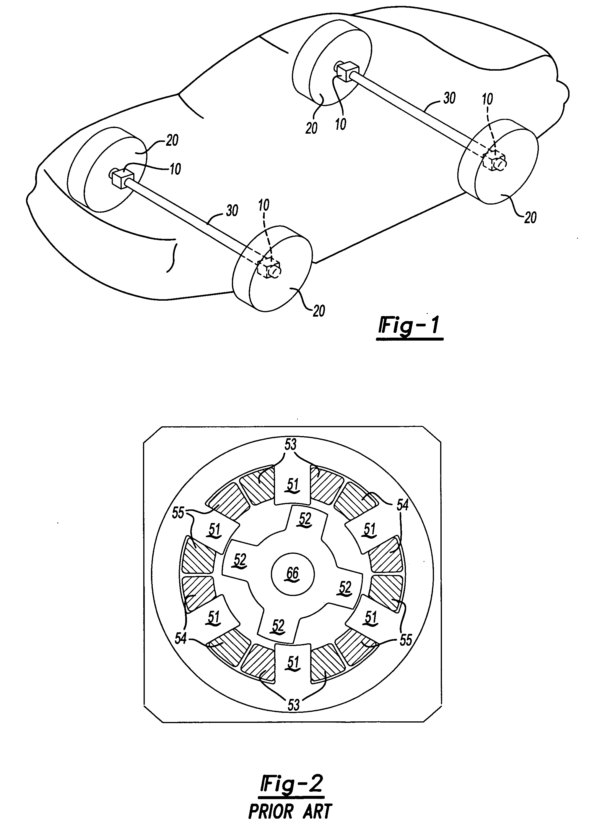
[0022]The embodiment of FIG. 1 relates to a traction motor for use in an electric drive train for an automobile. Traction motor 10 is placed on a shaft 30 near each of four wheels 20. In the illustrated example the motor is being used in a hybrid electromechanical braking system. The current invention could be utilized in any number of different applications, and provides benefits anywhere a switched reluctance transverse flux machine would be beneficial.

[0023]As shown in FIG. 2, known standard switched reluctance motors in the prior art are composed of a set of three phase windings 53, 54, 55, each of which is wound on a stator pole 51. Each switched reluctance machine design has a certain number of suitable combinations of stator poles 51 and rotor poles 52. The motor is excited (caused to move) by a sequence of current pulses applied at each phase winding 53, 54, 55. The individual phase windings 53, 54, 55 are consequentially energized, forcing the electric field within the swit...


PUM


Abstract

The present invention deals with a transverse flux machine of the switched reluctance variety. The transverse flux machine consists of multiple phases where each phase is spaced axially along the shaft. Axial spacing provides many benefits including a decreased weight and a capability to use simple wound bobbin coils for the windings. An embedded cooling loop is provided within the coils themselves. This cooling loop provides internal temperature regulation for the windings and allows for a higher efficiency among other benefits.

Description

BACKGROUND OF THE INVENTION[0001]This application relates to an improved motor, wherein the stator windings of a multi-phase motor are spaced axially along a rotational axis of the motor. In addition, a cooling fluid is circulated through the stator windings.[0002]Traction motors are often required to provide electrical to mechanical conversion for commercial vehicle drive trains. Typically the traction motors used in drive train applications have been three phase AC induction machines. A three phase AC induction machine is a machine that utilizes an induction motor to turn three phase electrical energy into mechanical motion. The primary reason for the use of AC induction machines as traction motors is that AC induction machines are easy to build and use well established technology. The fact that the technology behind AC induction machines is well established and has a large infrastructure allows them to be produced relatively cheaply.[0003]On the other hand, large cost, size, and ...

Claims


Application Information

Patent Timeline
Patent Type & Authority Applications(United States)
IPC IPC(8): H02K37/14H02K47/00H02K19/00H02K19/20H02K1/22
CPCH02K1/145B60L2220/50H02K3/24H02K16/00H02K19/06H02K2201/12B60L3/0061B60L15/20B60L2220/18B60L2220/44B60L2240/12B60L2240/36B60L2240/421B60L2240/423B60L2260/28H02K1/182Y02T10/64Y02T10/72
Inventor KRAMER, DENNIS A.
Owner ARVINMERITOR TECH
Learn More