Eureka AIR delivers breakthrough ideas for toughest innovation challenges, trusted by R&D personnel around the world.

Welding equipment for metallic materials and method for welding metallic materials

a welding equipment and metallic material technology, applied in welding/soldering/cutting articles, manufacturing tools, electric/magnetic/electromagnetic heating, etc., can solve the problems of difficult to obtain stable strength, difficult to obtain desired strength stably, and the effect of tempering becomes minimal, and achieves flexible heating treatment. , the effect of short time and simple configuration

Inactive Publication Date: 2011-12-15
NETUREN CO LTD +1
View PDF47 Cites 20 Cited by
  • Summary
  • Abstract
  • Description
  • Claims
  • Application Information

AI Technical Summary

Benefits of technology

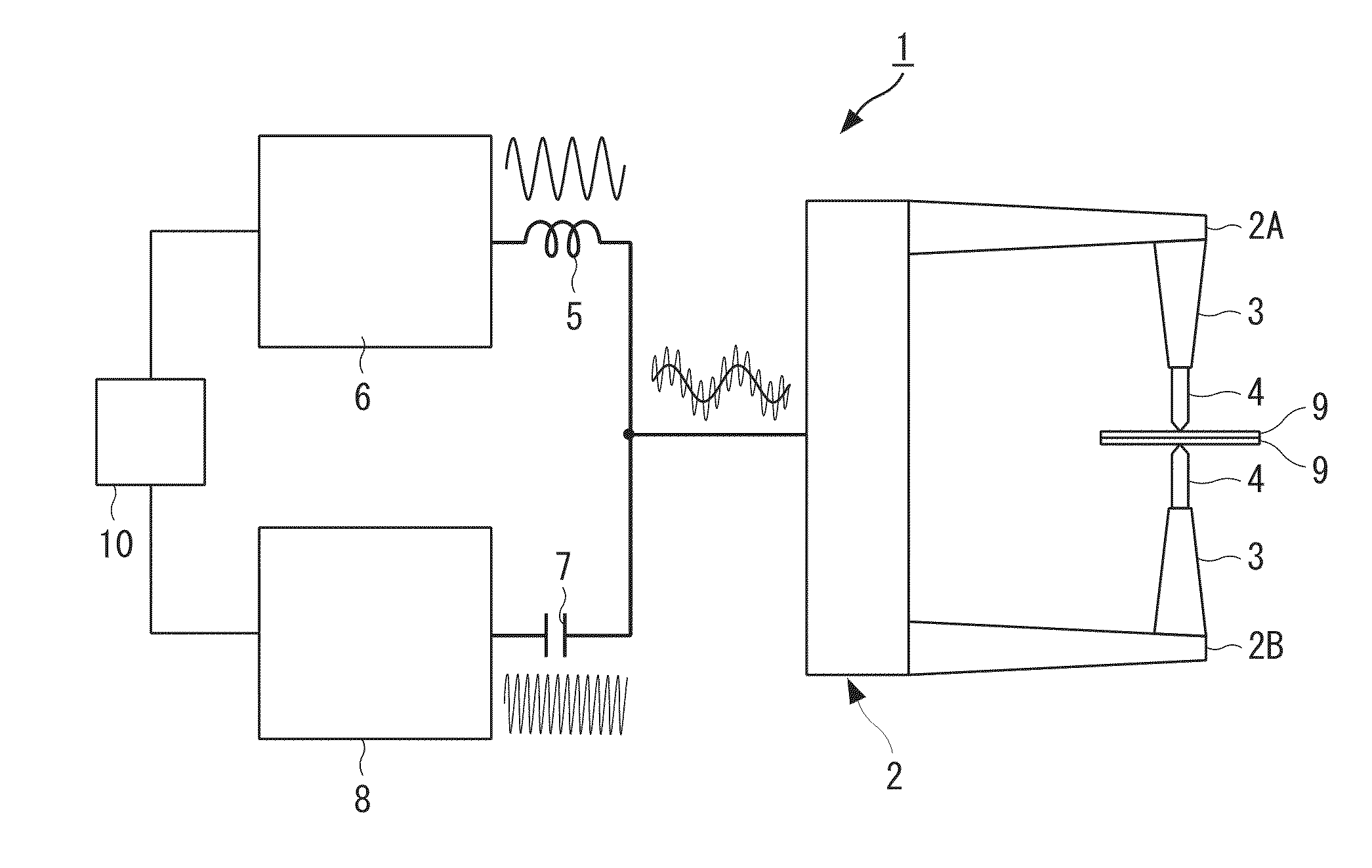
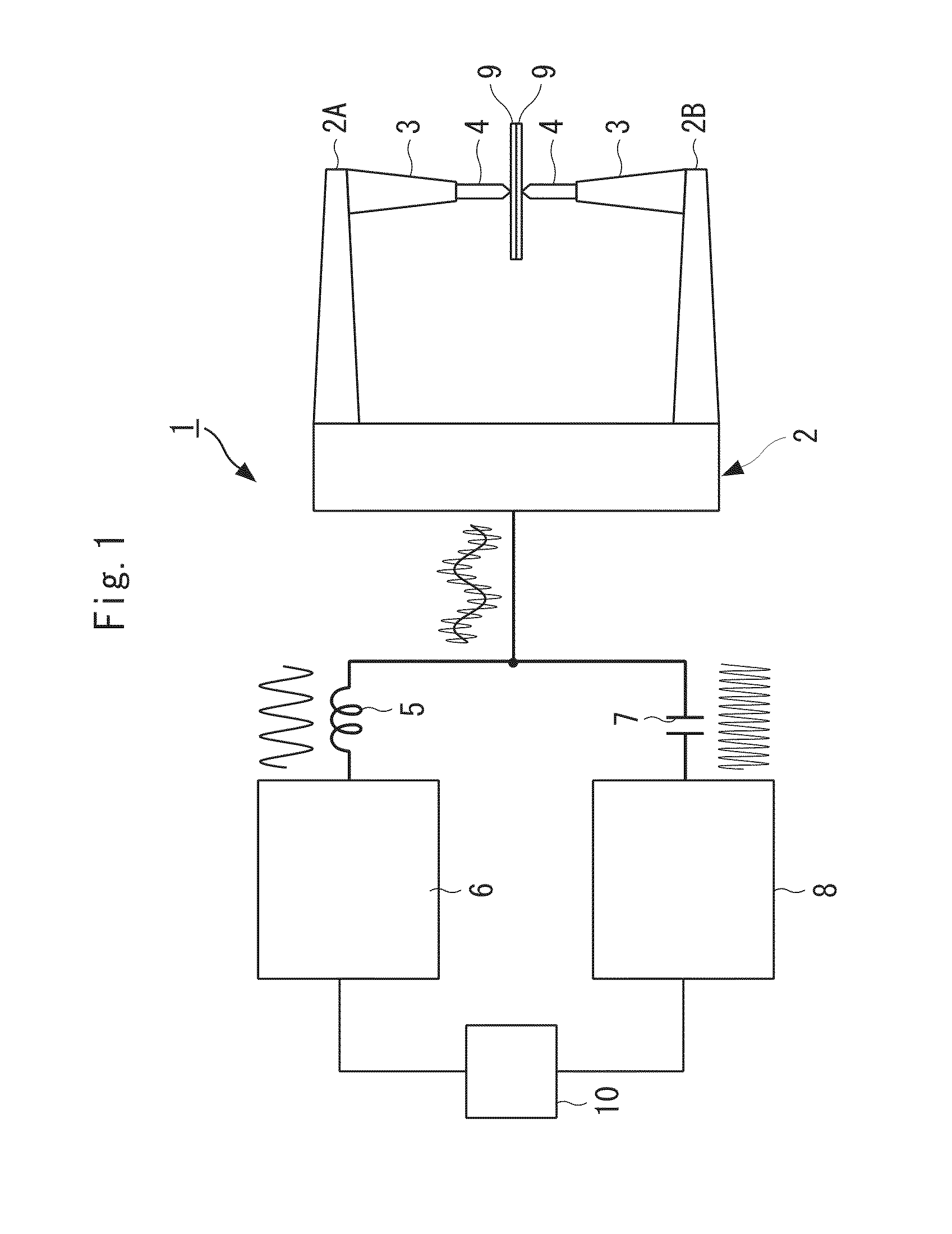
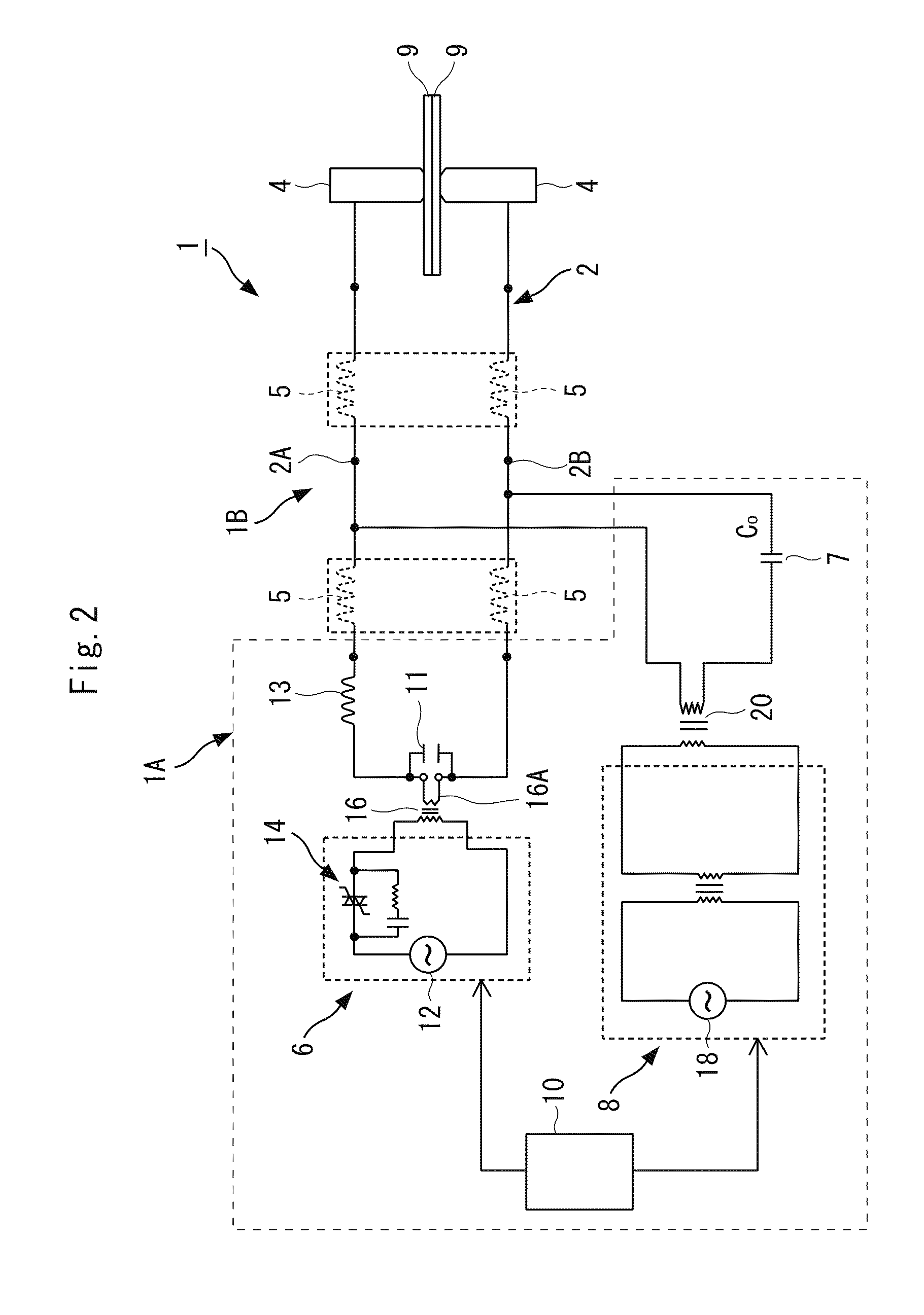
[0035]The present invention provides welding equipment of simple configuration, with a high-frequency power source connected to the electrodes of the welding equipment, capable of heating outer periphery of the electrodes using the same electrodes and performing heat treatment of the outer periphery of the nugget formed by spot welding in a short time. Furthermore, by changing the frequency of the high-frequency power source, flexible heating treatment can be performed.
[0036]According to the method for welding metallic materials of the present invention, a high-frequency power source can be connected to the electrodes for spot welding, metallic materials can be heated using the electrodes, and preheating of the metallic materials and the heating treatment of the outer peripheral region of the nugget formed by spot welding can be performed in a short time.

Problems solved by technology

It has been reported that in spot welding of high-tension steel plates, the tensile strength of a superposed joint increases as the strength of the joint material increases, but that the peel strength of a cross joint does not increase with the improvement of material strength, meaning that it is difficult to obtain stable strength.
In this case, however, the spot-weld region becomes extremely hard and brittle, and thus it is difficult to obtain desired strength stably.
Consequently, if tempering is performed by post-energization using existing welding equipment, the effect of tempering becomes minimal.
This problem is derived from the basic problem of resistance welding that efficient heating cannot be caused in a short time because the current density of the welded region decreases as the energized area increases after the formation of a nugget 54.

Method used


Image

  • Welding equipment for metallic materials and method for welding metallic materials
  • Welding equipment for metallic materials and method for welding metallic materials
  • Welding equipment for metallic materials and method for welding metallic materials

Examples


embodiment 1

[0180]The specific example of spot-welding the steel plates 9 with the welding equipment 1 for metallic materials of the present invention will hereafter be detailed.

[0181]Spot-welding of two steel plates 9 were performed. FIG. 21 illustrates the application of electric power from a low-frequency power source 6 and a high-frequency power source 8. The conditions of the steel plates 9, low-frequency power source 6, and high-frequency power source were as follows:

[0182]Steel plates 9: Thickness; 2 mm, Size; 5 cm×15 cm

[0183]Low-frequency power source 6: 50 Hz (Material of electrodes 4: copper, diameter: 6 mm), capacity: 50 kVA

[0184]Energization time of low-frequency power source 6: 0.3 to 0.5 sec.

[0185]High-frequency power source 8: 30 kHz, 50 kW output

[0186]Energization time of high-frequency power source 8: 0.3 to 0.6 sec.

[0187]The steel plates 9 contain carbon (C) in 0.19 to 0.29 weight %, as a component other than iron.

[0188]As shown in FIG. 21, preheating was performed for 0.3 sec...

embodiment 2

[0190]In embodiment 2, the power from the high-frequency power source 8 was applied together with the power from the low-frequency power source 6 for 0.3 sec. The high-frequency power was changed from 2.7 kW to 39.9 kW. The power from the low-frequency power source 6 was applied in the same manner as embodiment 1.

embodiment 3

[0191]In embodiment 3, the power from the high-frequency power source 8 was applied for 0.3 sec. immediately after the completion of application of the power from the low-frequency power source 6. The high-frequency power was changed from 2.7 kW to 39.9 kW. The power from the low-frequency power source 6 was applied in the same manner as Embodiment 1.


PUM

PropertyMeasurementUnit
frequencyaaaaaaaaaa
frequencyaaaaaaaaaa
diameteraaaaaaaaaa

Abstract

A welding equipment for metallic materials capable of performing heat treatment such as tempering based on partial heating in spot welding is provided. The welding equipment 1 sandwiches metallic materials 9 with a pair of electrodes 4, 4, and heats different regions of the metallic materials 9 by energization, with the pair of electrodes 4, 4 maintained at the same position with respect to the metallic materials 9. The welding equipment includes a first heating means 6 connected to the pair of electrodes 4, 4 for heating and welding the internal region of the circle defined by projecting the cross-sectional area of the axis of the electrodes on the metallic materials by applying power having a low first frequency, a second heating means 8 for heating a ring-shaped region along the circle by applying power having a second frequency that is higher than the first frequency, and an energization control unit 10 for independently controlling the first and the second heating means 6, 8.

Description

TECHNICAL FIELD[0001]The present invention relates to welding equipment for metallic materials and a method for welding metallic materials. More specifically, the invention relates to the welding equipment that forms a nugget in a metallic work using electric power from a power source for spot welding and heats the work with electric power from a high-frequency power source, and a method for welding metallic materials.BACKGROUND ART[0002]Spot-welding equipment is used to weld steel plates kept in contact with each other. FIG. 24 is a cross-sectional view illustrating the spot welding of steel plates 50. As shown in FIG. 24, spot-welding of the steel plates 50 is performed by sandwiching the plates contacting each other with a pair of electrodes 52, and by applying a given force to the electrodes 52 in the direction of the arrow to pressurize the steel plates 50.[0003]A large current on the order of kA is then fed to the electrodes 52 while the pressurized state is maintained to melt...

Claims


Application Information

Patent Timeline
Patent Type & Authority Applications(United States)
IPC IPC(8): H05B6/06B23K11/24
CPCB23K11/115B23K11/24B23K2203/04B23K11/312B23K2201/18B23K11/26B23K2101/18B23K2103/04B23K11/11B23K11/36B23K11/241B23K13/08
Inventor KANAI, TAKAHIKOHATTA, MUNEHISAIKUTA, FUMIAKIKAWASAKI, KAZUHIRONAKANISHI, EIZABUROYOSHIDA, TSUYOSHINAGAI, KOTOBUHAYAKAWA, MASAOITAGAKI, TAKEHIKO
Owner NETUREN CO LTD
Why Eureka
Eureka Blog
Learn More