
Timing pulley

a timing pulley and timing belt technology, applied in the direction of gearing elements, belts/chains/gearrings, hoisting equipments, etc., can solve the problems of inefficiency, time-consuming and laborious, and the process of fabricating the timing belt and the timing pulley is difficult to achieve, and achieves the effect of reducing the weight, eliminating noise, and facilitating fabricated

Inactive Publication Date: 2011-12-08
TSUBAKIMOTO CHAIN CO
View PDF6 Cites 5 Cited by
  • Summary
  • Abstract
  • Description
  • Claims
  • Application Information

AI Technical Summary

Benefits of technology

[0024]According to the first aspect of the timing pulley of the invention and the seventh aspect of the motion transmitting mechanism, because the timing pulley includes the cylindrical timing hub which is fitted around a power transmitting shaft, the pair of flange members provided apart on the both end portions of the timing hub and the plurality of engagement pins disposed on the peripheral edge portion of the pair of flange members in the circumferential direction thereof so as to extend between and through each of the flange members and so as to engage with the mating teeth of the timing belt, it is possible to provide a timing pulley whose weight is light, whose pulley structure is simple and which excels in workability. In addition, the timing pulley has the following advantageous effects peculiar to the present invention.
[0025]That is, because the timing pulley of the first and seventh aspects of the invention includes the plurality of engagement pins disposed on the peripheral edge portions of the pair of flange members in the circumferential direction thereof so as to extend between and through each of the flange members and so as to engage with the mating teeth of the timing belt, and because each mating portion mating with the mating tooth of the timing belt is only the engagement pin and the part inside of the engagement pin is a space opened to the outside, it becomes possible to reduce its weight as compared to a solid timing pulley currently known in the art. It is also possible to eliminate noise otherwise caused by compression of air generated in a closed space because such closed space between the mating portion of the timing pulley and the mating tooth of the timing belt is eliminated.
[0026]Still more, because each mating portion of the timing pulley can be made by using the engagement pin that can be fabricated easily, it becomes unnecessary to fabricate the timing pulley by using such machine tool as a hobbing machine and to considerably improve productivity in fabricating the timing pulley.
[0027]According to the second aspect of the timing pulley of the invention and the eighth aspect of the motion transmitting mechanism, because the engagement pins are attached to the flange members removably through the pin inserting holes disposed along the circumferential direction of the flange members, it becomes easier to attach the engagement pins and to simplify a timing pulley fabricating process.
[0028]Still more, even if a part of the timing pulley is broken, it is unnecessary to replace the entire timing pulley and a damaged timing pulley can be repaired by merely replacing the very engagement pin. Accordingly, it becomes easy to maintain the timing pulley and to reduce waste of its material.
[0029]According to the third aspect of the timing pulley of the invention and the ninth aspect of the motion transmitting mechanism, because the flange members are removably fixed to the timing hub by using the bolt fastening means, it becomes unnecessary to perform such cumbersome works as using a hobbing machine in the timing pulley fabricating process because the timing hub and the flange members can be built easily by the bolt fastening means.

Problems solved by technology

Because the mating tooth of the toothed belt and the mating portion of the timing pulley of these configurations have a unique shape, e.g., having an involute curve so that the toothed belt engages smoothly with the timing pulley for a long period of time, the process of fabricating the toothed belt and the timing pulley, i.e., workability, is inefficient because special machining tools and special skill are required.
Additionally, there is also a problem in that the timing pulley 500 often generates noise because air remaining near the bottom of each mating portion 501 is compressed when the timing belt TB engages with the timing pulley 500.
In this case, while a structure such as a groove or a concavo-convex portion for allowing the air to escape to the outside is provided either in the mating tooth TB1 of the timing belt TB or the mating portion of the timing pulley 500, there is a problem that it requires another labor in forming such mechanism.

Method used


Image

  • Timing pulley
  • Timing pulley
  • Timing pulley

Examples


first embodiment

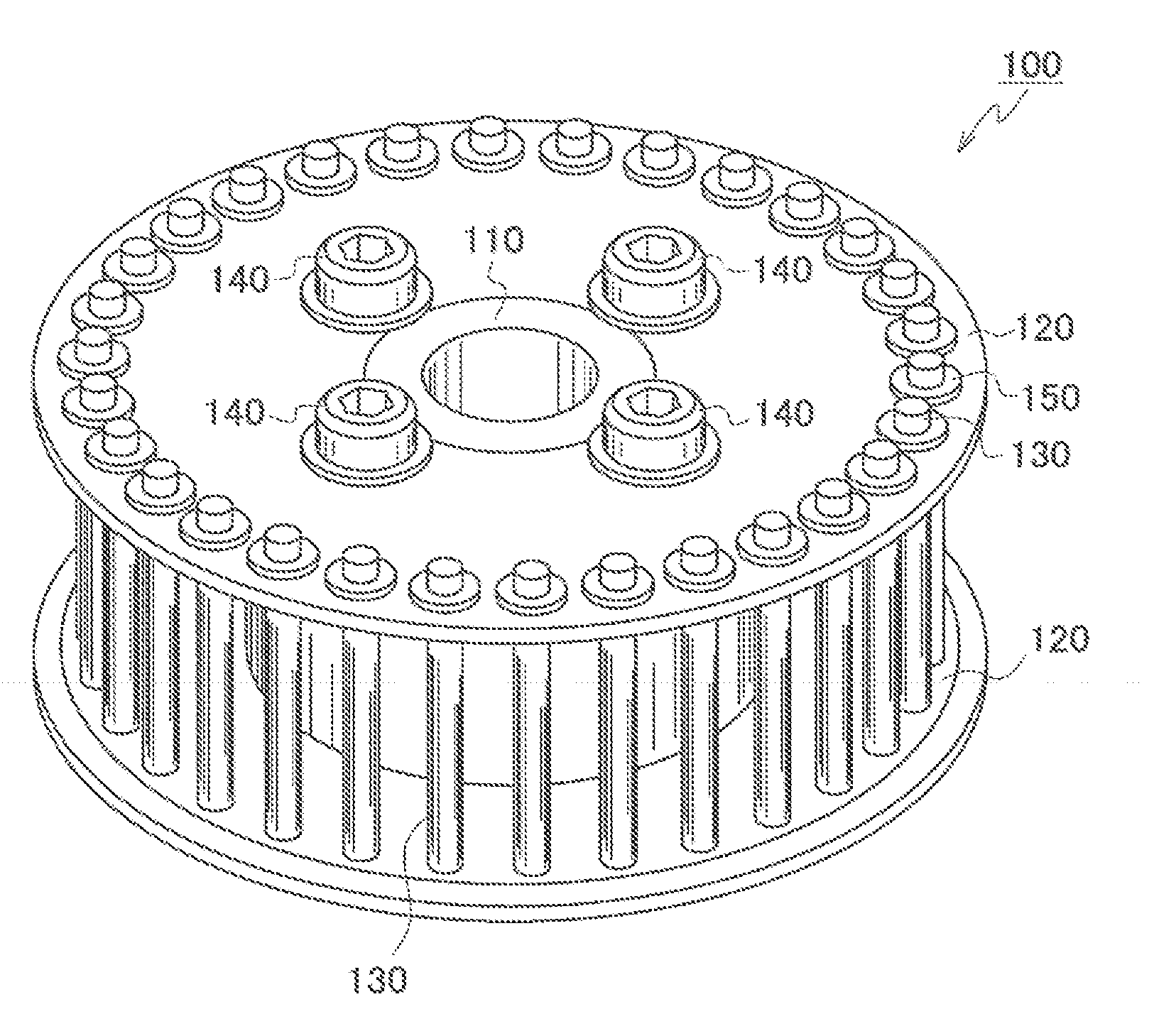
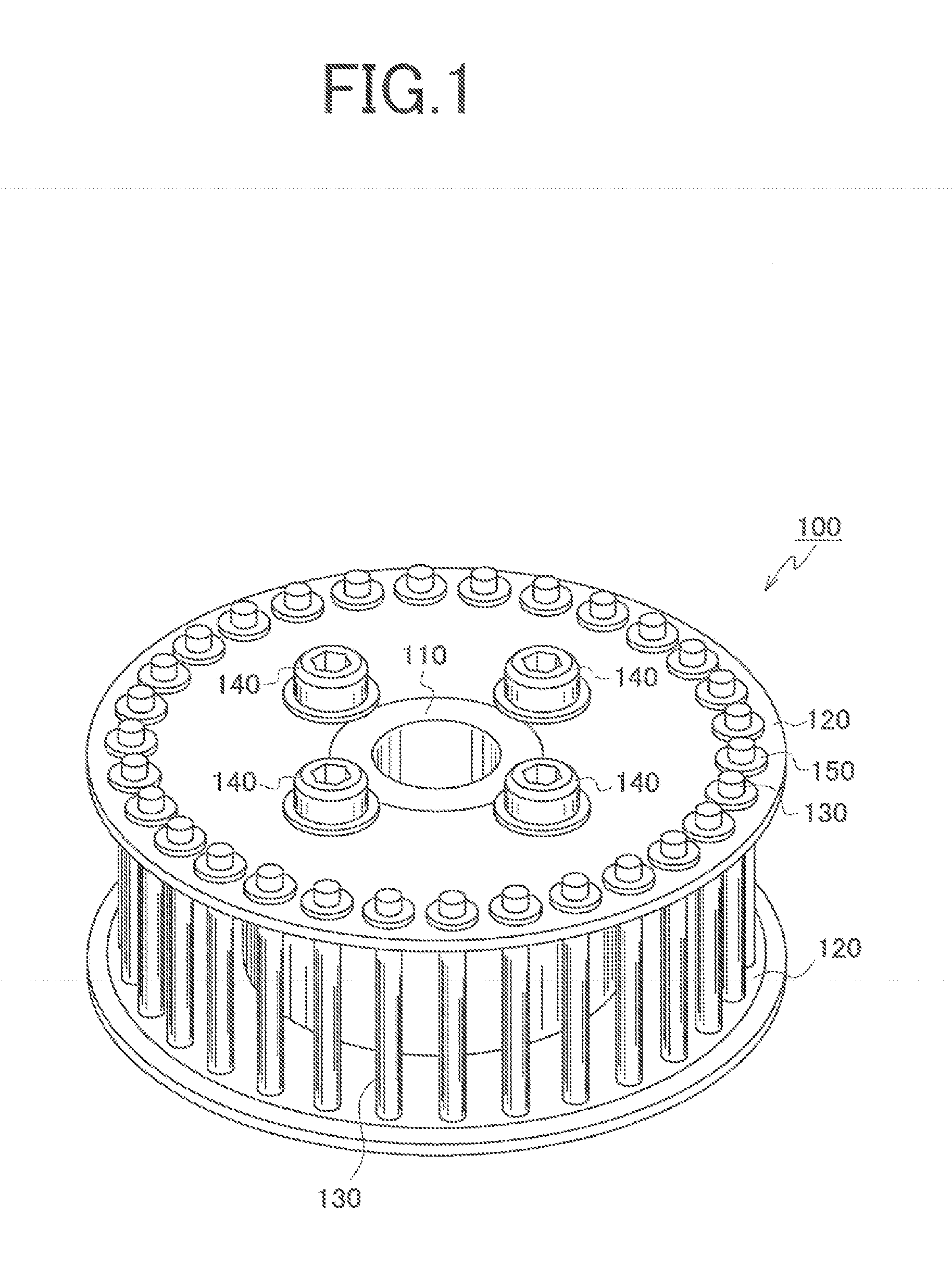
[0043]A first embodiment of a timing pulley of the invention will be explained with reference to FIGS. 1 through 6.

[0044]Here, FIG. 1 is a schematic view of the timing pulley of the first embodiment, FIG. 2 is a front view of the timing pulley shown in FIG. 1, FIG. 3 is a section view of the timing pulley shown in FIG. 2, FIG. 4 is a partially enlarged view of an engagement pin attaching part shown in FIG. 3, FIG. 5 is a partially enlarged view showing a different mode of the engagement pin attaching part shown in FIG. 3 and FIG. 6 is an explanatory view explaining operations of the timing pulley shown in FIG. 1.

[0045]The timing pulley 100 of the first embodiment of the invention is used in a timing belt system which may be used in a variety of settings, such as driving an engine auxiliary device for example.

[0046]The timing pulley 100 comprises a cylindrical and metallic timing hub 110 which is fitted around a power transmitting shaft. Then, circular flange members 120 are provided...

second embodiment

[0056]Next, a timing pulley 200 according to a second embodiment of the invention will be explained with reference to FIG. 7.

[0057]The timing pulley of the second embodiment is different from the first embodiment only in the mode for attaching the engagement pins 130 and other components are the same with those of the second embodiment, so that an overlapped explanation of members of the second embodiment with those of the timing pulley 100 of the first embodiment will be omitted here by denoting reference numerals in 200s.

[0058]FIG. 7 is an explanatory view explaining operations of the timing pulley of the second embodiment of the invention. The timing pulley 200 of the second embodiment forms one unit pitch P by three engagement pins 230 for example. More specifically, an interval A is formed between the engagement pins 231 and 232, an interval B is formed between the engagement pins 232 and 233 and an interval C is formed between the engagement pins 233 and a next engagement pin ...


PUM


Abstract

There is provided a timing pulley whose noise is low, which is light-weight, whose pulley structure is simple and which excels in workability. The timing pulley comprises a cylindrical timing hub which is fitted around a power transmitting shaft, a pair of flange members provided apart on both end portions of the timing hub and a plurality of engagement pins disposed on peripheral edge portions of the pair of flange members in the circumferential direction thereof so as to extend between and through each of the flange members and so as to engage with mating teeth of a timing belt.

Description

CROSS REFERENCE TO RELATED APPLICATIONS[0001]This application claims the foreign priority benefit under Title 35, United States Code, §119 (a)-(d) of Japanese Patent Application No. 2010-128965, filed on Jun. 4, 2010 in the Japan Patent Office, the disclosure of which is herein incorporated by reference in its entirety.BACKGROUND OF THE INVENTION[0002]1. Field of the Invention[0003]The present invention relates to a motion transmitting mechanism for transmitting rotational movement by means of a timing belt and more specifically to a timing pulley used together with the timing belt.[0004]2. Related Art[0005]Hitherto, a rotational motion transmitting mechanism comprising a toothed belt such as a timing belt and a timing pulley has been used as a convenient and reliable motion transmitting means which have been used in various applications such as driving an engine auxiliary machine.[0006]The motion transmitting mechanisms often include a toothed belt in which mating teeth are formed ...

Claims


Application Information

Patent Timeline
IPC IPC(8): F16H55/12F16H55/17
CPCF16H55/171F16H55/10
Inventor SAKAMOTO, HIROSHI
Owner TSUBAKIMOTO CHAIN CO
Learn More