Base station apparatus, terminal device, and rank setting method

a technology of rank indication and base station, which is applied in the direction of instruments, data switching networks, frequency-division multiplexes, etc., can solve problems such as lowering throughput, and achieve the effect of suppressing the decrease of throughput and reducing the amount of control information

Inactive Publication Date: 2011-12-08
PANASONIC CORP
View PDF1 Cites 3 Cited by
  • Summary
  • Abstract
  • Description
  • Claims
  • Application Information

AI Technical Summary

Benefits of technology

[0023]According to the present invention, it is possible to reduce the amount of control information about the rank indication of an additional band and suppress decrease of throughput, in a radio communication system supporting band aggregation.

Problems solved by technology

Therefore, in combination of band aggregation and use of multiple antennas, although it is possible to optimize setting parameters per band by controlling setting parameters such as rank indications individually per band, a problem of causing lowered throughput due to increased signaling arises.

Method used


Image

  • Base station apparatus, terminal device, and rank setting method
  • Base station apparatus, terminal device, and rank setting method
  • Base station apparatus, terminal device, and rank setting method

Examples


embodiment 1

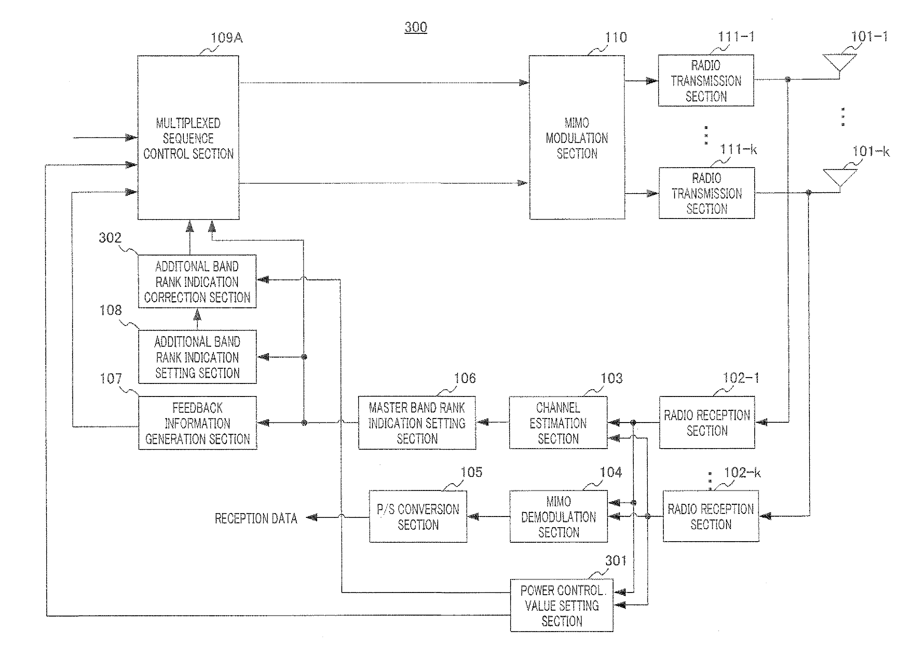
[0043]FIG. 4 is a block diagram showing a configuration of base station 100 according to Embodiment 1 of the present invention.

[0044]Radio reception sections 102-1 to 102-k receive a data signal and a reference signal for measuring channel quality (hereinafter simply referred to as measurement reference signal) transmitted from a terminal apparatus via antennas 101-1 to 101-k (k is an integer of 2 or greater). Radio reception sections 102 to 102-k converts the received signal into a baseband signal by performing radio reception processing such as band limitation, down-conversion, and analog to digital (A / D) conversion, and, out of the baseband signal, outputs a measurement reference signal to channel estimation section 103 and outputs the data signal to multiple input multiple output (MIMO) demodulation section 104. Here, the measurement reference signal is transmitted from a terminal (described later) in both frequency bands of the master band and an additional band.

[0045]Channel e...

embodiment 2

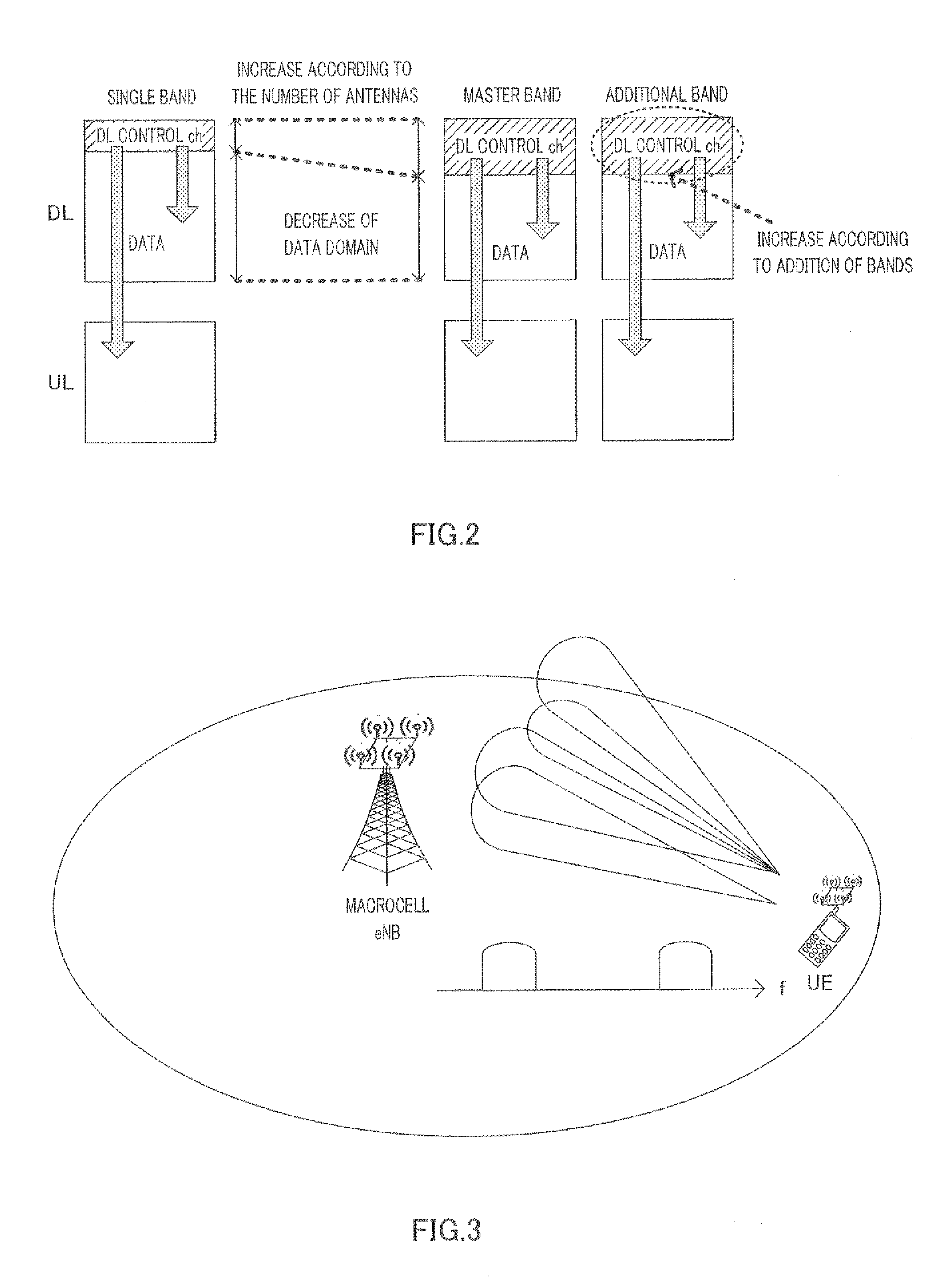
[0082]A case has been described with Embodiment 1 where by paying attention to the characteristics that there is a distribution of eigenvalues of a channel matrix for each band, and the number of eigenvalues that achieves certain channel quality (rank indication that can be used) varies per band, additional band rank indication setting section 108 (206) is configured to set an additional band rank indication using the frequency band and rank indication of the master band and the frequency band of the additional band.

[0083]By the way, Non-Patent Literature 6 or Non-Patent Literature 7 disclose path loss (PL) equations, and, from these PL equations, it is known that “path loss becomes greater as the frequency is higher.” That is, when transmission is performed using the same transmission power, reception power at a receiving end becomes smaller as the frequency is higher, which, in other words, means that channel quality deteriorates as the frequency is higher. Therefore, when taking ...


PUM


Abstract

A base station apparatus, in a wireless communication system supporting band aggregation, able to limit drops in throughput while lowering the amount of control information for the rank of an added band; and a terminal device and rank setting method of the same. An added band rank setting unit (108) includes a memory (1084) which defines, as a rank and from the eigenvalue distributions of the channel matrices of the master band and added band, the number of eigenvalues of the channel matrix of the added band that satisfy channel quality according to the rank of the master band, and associates that number with the frequency band and rank of the master band and the frequency band of the added band. The added band rank setting unit (108) acquires, from the memory (1084), the rank that is associated with the information on the frequency band and rank of the master band and the information on the frequency band of the added band, and sets the same as the rank of the added band.

Description

TECHNICAL FIELD[0001]The present invention relates to a base station apparatus, a terminal apparatus, and a rank indication setting method in a radio communication system supporting band aggregation.BACKGROUND ART[0002]In mobile radio communication, an approach to realize high transmission has been constantly under consideration in line with demands from the market. In long term evolution (LTE)-advanced, achievement of a downlink peak data rate of 1 Gbps and an uplink peak data rate of 500 Mbps are demanded (see Non-Patent Literature 1). Therefore, for example, in Non-Patent Literature 2, to achieve a high speed peak data rate, further broadbandization and further use of multiple antennas are under consideration.[0003]For further broadbandization, taking into account the flexibility in securing a band, an approach to broadbandization for combining a plurality of bands is under consideration, instead of realizing broadbandization in a single band, such as a 100 MHz band. This approac...

Claims


Application Information

Patent Timeline
Patent Type & Authority Applications(United States)
IPC IPC(8): H04W72/06H04W24/00H04W72/54
CPCH04B7/0413H04B7/0697H04W72/087H04W28/20H04L25/0248H04W72/543
Inventor SAITO, YOSHIKOHOSHINO, MASAYUKIMIYOSHI, KENICHINAKAO, SEIGOIMAMURA, DAICHI
Owner PANASONIC CORP
Why Eureka
Try Eureka