
Impact sensitive damper

a damper and impact-sensitive technology, applied in the direction of shock absorbers, vibration dampers, springs/dampers, etc., can solve problems such as deteriorating ride comfort, and achieve the effect of improving ride comfort and damping for

Active Publication Date: 2011-12-08
HL MANDO CORP
View PDF11 Cites 8 Cited by
  • Summary
  • Abstract
  • Description
  • Claims
  • Application Information

AI Technical Summary

Benefits of technology

[0018]The present invention has been made in an effort to provide an impact sensitive damper in which both of a dish shaped spring and a disk shaped spring are used in a body valve of the damper to achieve smooth improvement of damping force at the time of conversion from a low speed operating section of the damper into a high speed operating section thereof, such that handling stability and improvement of ride comfort may be simultaneously achieved.
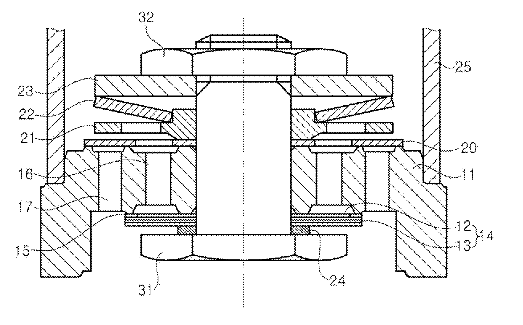
[0019]According to an exemplary embodiment of the present invention, there is provided an impact sensitive damper improving ride comfort by decreasing damping force when impact is applied to a vehicle, the impact sensitive damper including: a body valve body having compression channels and expansion channels formed therein; a fastener vertically penetrating through the body valve body; a dish shaped spring interposed between an upper portion of the body valve body and the fastener; and a disk shaped spring interposed between a lower portion of the body valve body and the fastener, wherein at the time of compression stroke when the impact is applied to the damper, the fastener is relatively displaced with respect to the body valve body due to elastic deformation of the dish shaped spring, such that the disk shaped spring and the lower portion of the body valve body are spaced apart from each other, thereby increasing a channel area of operating fluid.

Problems solved by technology

Therefore, when large impact is transferred to the damper, a limitation in deformation of the multi-plate disk 68 occurs, such that the damping force rapidly increases, thereby deteriorating the ride comfort.

Method used


Image

  • Impact sensitive damper
  • Impact sensitive damper
  • Impact sensitive damper

Examples


Embodiment Construction

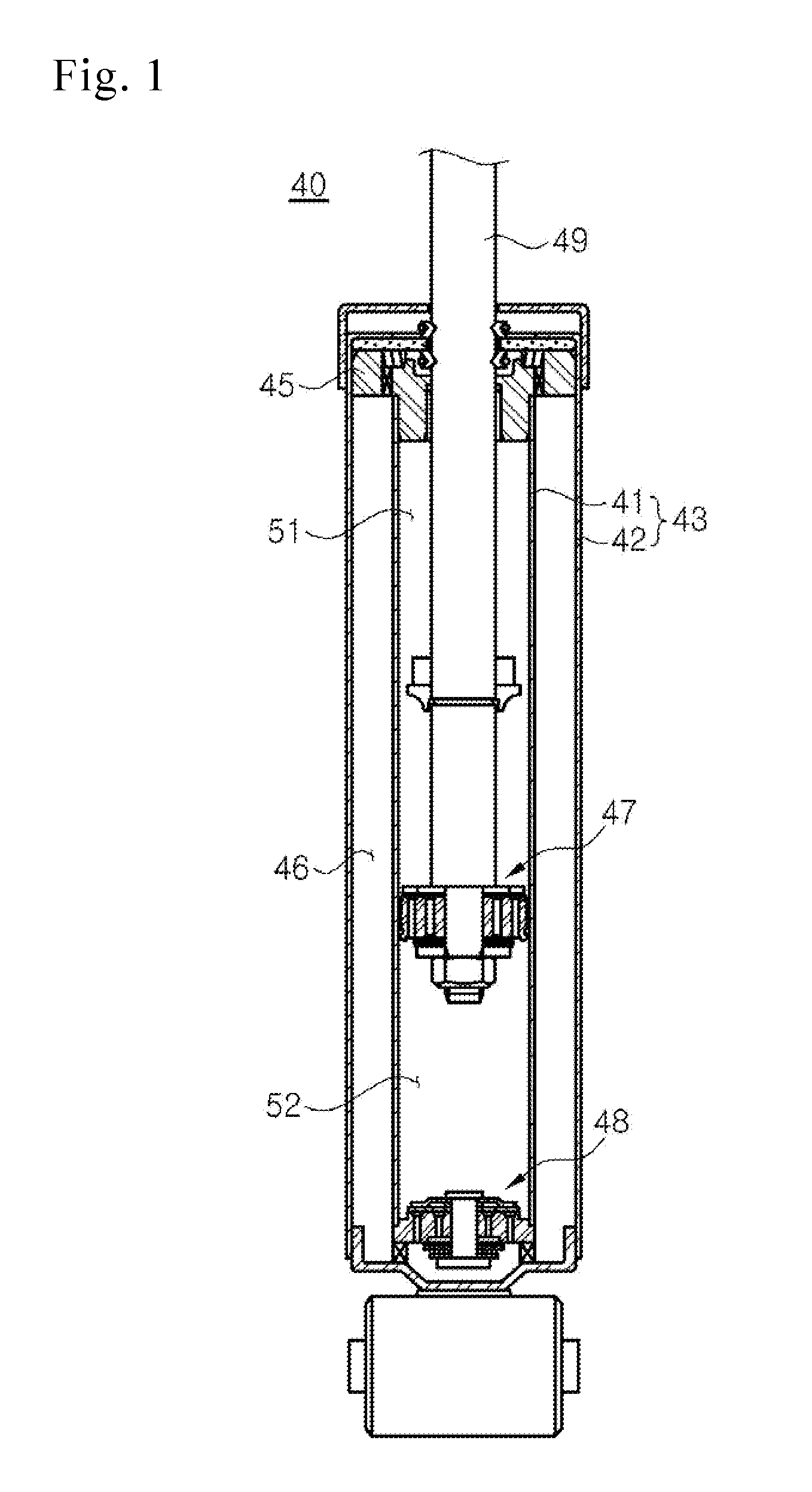
[0029]Hereinafter, an impact sensitive damper according to an exemplary embodiment of the present invention will be described in detail with reference to the accompanying drawings. Damping force may be generated in a damper at the time of both of expansion stroke and compression stroke. However, since the present invention relates to the damping force at the time of the compression stroke, a body valve having an influence on generation of the damping force at the time of the compression stroke will be mainly described.

[0030]A cross-sectional view of a body valve assembly of an impact sensitive valve according to the prevent invention is shown in FIG. 3.

[0031]As shown in FIG. 3, an impact sensitive damper according to the prevent invention includes a cylindrical cylinder 25 having operating fluid filled therein and a body valve body 11 mounted in the cylinder 25 and having compression channels 16 and expansion channels 17 formed therein, having a predetermined interval therebetween. ...


PUM


Abstract

Disclosed herein is an impact sensitive damper damping vibration transferred from a road surface to a vehicle, and more particularly, to an impact sensitive damper in which handling stability may be achieved in a low speed operating section of the damper and improvement of ride comfort may be achieved in a high speed operating section thereof. According to an exemplary embodiment of the present invention, there is provided an impact sensitive damper improving ride comfort by decreasing damping force when impact is applied to a vehicle, the impact sensitive damper including: a body valve body having compression channels and expansion channels formed therein; a fastener vertically penetrating through the body valve body; a dish shaped spring interposed between an upper portion of the body valve body and the fastener; and a disk shaped spring interposed between a lower portion of the body valve body and the fastener, wherein at the time of compression stroke when the impact is applied to the damper, the fastener is relatively displaced with respect to the body valve body due to elastic deformation of the dish shaped spring, such that the disk shaped spring and the lower portion of the body valve body are spaced apart from each other, thereby increasing a channel area of operating fluid.

Description

[0001]This application claims priority from and the benefit of Korean Patent Application No. 10-2010-0052725, filed on JUNE 4, 2010, which is hereby incorporated by reference for all purposes as if fully set forth herein.BACKGROUND[0002]1. Technical Field[0003]The present invention relates to an impact sensitive damper damping vibration transferred from a road surface to a vehicle, and more particularly, to an impact sensitive damper in which handling stability may be achieved in a low speed operating section of the damper and improvement of ride comfort may be achieved in a high speed operating section thereof.[0004]2. Description of the Related Art[0005]Generally, since vibration or impact is continuously applied from a road surface through wheels during driving of a vehicle, a damping device is installed between a car body and a car axis to prevent the impact or the vibration from being directly transferred to the car body, thereby improving ride comfort and to suppress irregular...

Claims


Application Information

Patent Timeline
Patent Type & Authority Applications(United States)
IPC IPC(8): F16F9/50F16F9/508F16F9/516
CPCF16F9/3485
Inventor KIM, HONG SIG
Owner HL MANDO CORP
Learn More