Luminaire cooling apparatus

a technology of cooling apparatus and aluminaire, which is applied in the field of exterior area lighting, can solve the problems that traditional cooling for outdoor area lighting such as street lights has failed to provide either adequate cooling or adequate control of energy costs

Inactive Publication Date: 2011-12-01
HELLA KG HUECK & CO
View PDF6 Cites 9 Cited by
  • Summary
  • Abstract
  • Description
  • Claims
  • Application Information

AI Technical Summary

Benefits of technology

[0006]An outdoor area light has housing, a light source comprised of a printed circuit board, a plurality of LEDs, and a heat sink. The heat sink is disposed in thermally conductive proximity to said light source to conduct heat away from it for temperature control. The light source and heat sink are mounted in the housing. A passive impeller is mounted on the housing. A separate active impeller is also mounted on the housing. A conduit for air is in fluid communication with the active impeller and disposed to direct cooling air over the light source and / or the heat sink. The printed circuit board and / or the heat sink and / or their mounts have holes through them. The holes define fluid throughways disposed to convect heat away from the light source via air moving through the throughways. The fluid throughways may be sufficiently aligned to maintain minimally turbulent air flow there through and across the light source and may be sufficiently aligned to establish laminar flow through them. In high heat, the active impeller is engaged to cool the light; otherwise the passive impeller keeps the light cool.

Problems solved by technology

Traditional cooling for outdoor area lighting such as street lights has failed to provide either adequate cooling or adequate control of energy costs.

Method used


Image

  • Luminaire cooling apparatus
  • Luminaire cooling apparatus
  • Luminaire cooling apparatus

Examples


Embodiment Construction

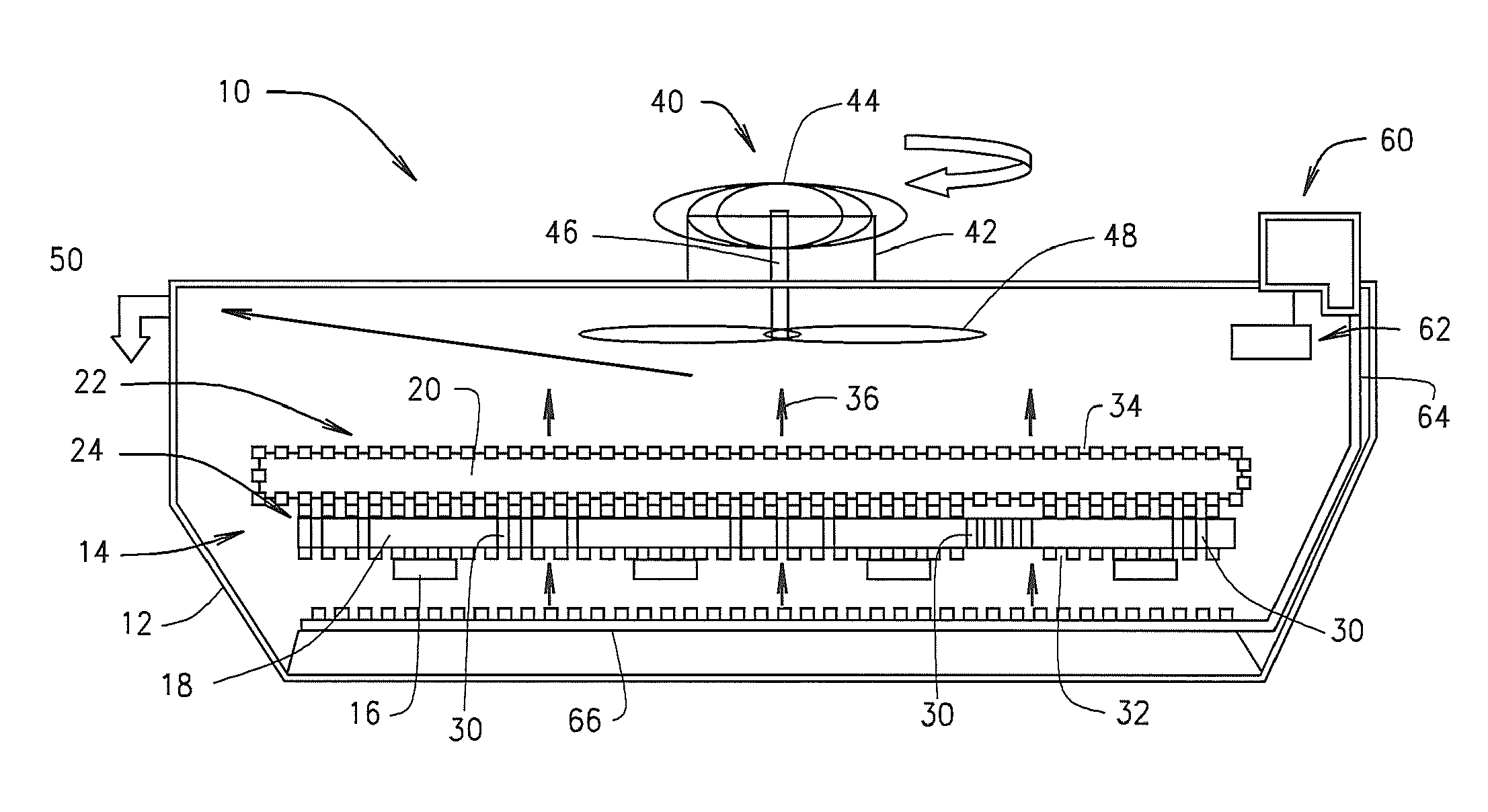
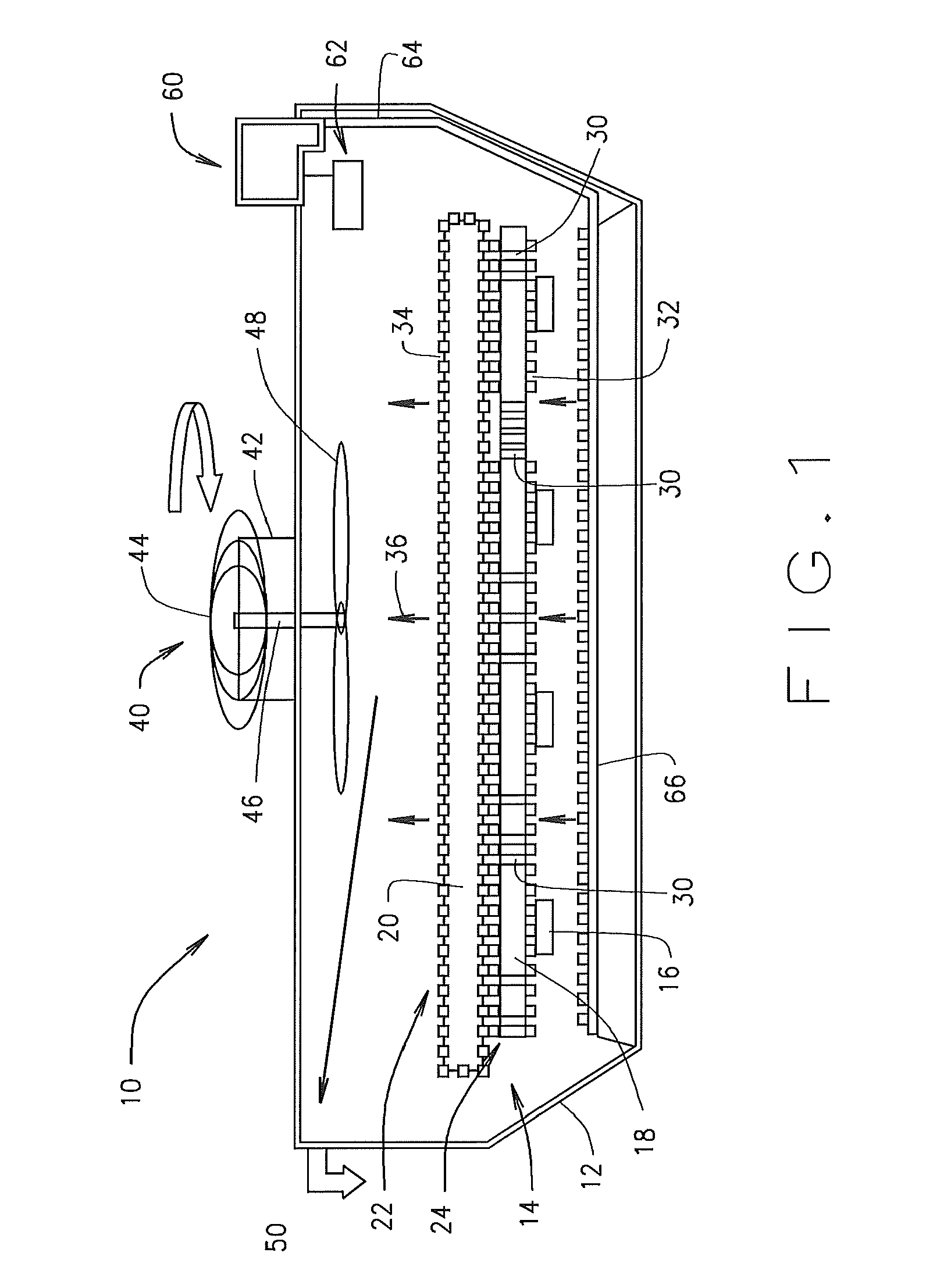
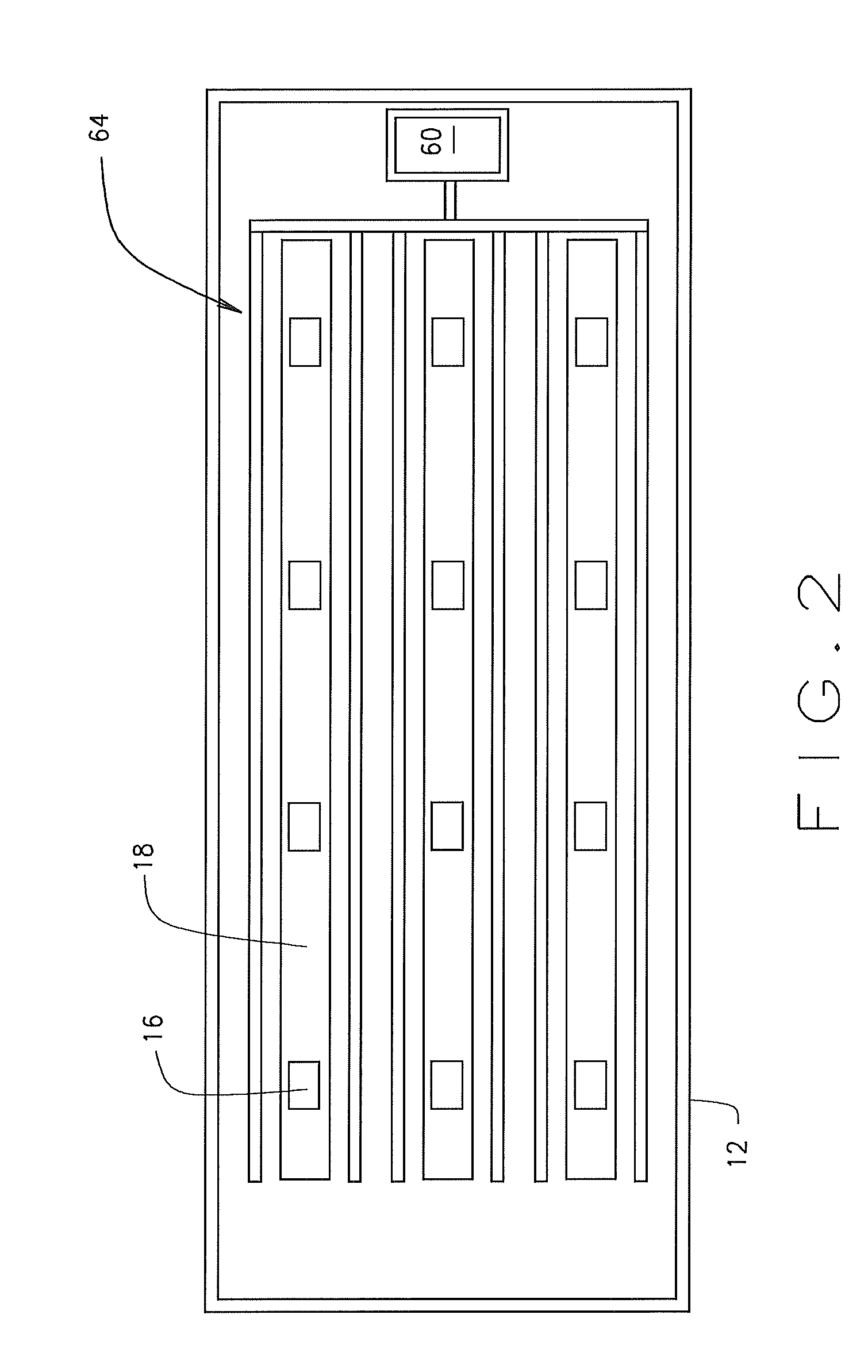
[0011]Referring now to the drawings in which like reference numbers indicate like elements, the Luminaire 10, for example, a street light, of the present invention is comprised of a housing 12 and within it a light source 14. The light source 14 is an assembly comprised of at least a plurality of LEDs 16 mounted to, powered through and / or controlled by a printed circuit board 18. A heat sink 20 is mounted with, on or near the light source 14 in sufficient proximity to thermally conduct heat from said light source 14.

[0012]Each of said printed circuit board 18 and heat sink 20 are mounted with a mounting element 22, 24, which may be individual for each of the PCB 18 and heat sink 20, or which may be integral. For example, the PCB 18 may be mounted with and substantially surrounded by copper cladding 22.

[0013]Within PCB 18 are a plurality of throughholes 30. Within the mounting / cladding 22 of the PCB there are also a plurality of holes 32 beneath the PCB 18. Within the heat sink mount...


PUM


Abstract

An outdoor area light has a housing, a light source comprised of a printed circuit board, a plurality of LEDs, and a heat sink. The heat sink is disposed in thermally conductive proximity to said light source to conduct heat away from it for temperature control. The light source and heat sink are mounted in the housing. A passive impeller is mounted on the housing. A separate active impeller is also mounted on the housing. A conduit for air is in fluid communication with the active impeller and disposed to direct cooling air over the light source and/or the heat sink. The printed circuit board and/or the heat sink and/or their mounts have holes through them. The holes define fluid throughways disposed to convect heat away from the light source via air moving through the throughways. The fluid throughways may be sufficiently aligned to establish laminar flow through them. In high heat, the active impeller is engaged to cool the light; otherwise the passive impeller keeps the light cool.

Description

CROSS-REFERENCE[0001]This application claims priority to U.S. Provisional Patent application No. 61 / 348,555 filed May 26, 2010.BACKGROUND OF THE INVENTION[0002]1. Field of the Invention[0003]The invention is in the field of exterior area lighting, particularly streetlights.[0004]2. Related Art[0005]Traditional cooling for outdoor area lighting such as street lights has failed to provide either adequate cooling or adequate control of energy costs. With newer technologies such as light emitting diodes (“LEDs”) providing greater energy efficiencies for a given quantity of light output, achieving corresponding cooling efficiencies would be advantageous.SUMMARY OF THE INVENTION[0006]An outdoor area light has housing, a light source comprised of a printed circuit board, a plurality of LEDs, and a heat sink. The heat sink is disposed in thermally conductive proximity to said light source to conduct heat away from it for temperature control. The light source and heat sink are mounted in the...

Claims


Application Information

Patent Timeline
Patent Type & Authority Applications(United States)
IPC IPC(8): F21S4/00F21V29/00
CPCF21W2131/103F21Y2105/001F21V29/83F21V29/673F21Y2101/02F21Y2105/10F21Y2115/10
Inventor SAXENA, SANDEEP
Owner HELLA KG HUECK & CO
Why Eureka
Try Eureka