
Method for Coupling a Machine Frame of an Earth Working Machine to a Working Device, Earth Working Machine, and Connecting Apparatus for the Method

a technology of earth working machine and working device, which is applied in the direction of roads, roads, constructions, etc., can solve the problems of large amount and considerable mechanical load on the participating centering formation, and achieve the effect of simplifying the alignment of the receiving portion and the working devi

Active Publication Date: 2021-01-21
WIRTGEN GMBH
View PDF0 Cites 3 Cited by
  • Summary
  • Abstract
  • Description
  • Claims
  • Application Information

AI Technical Summary

Benefits of technology

This approach reduces the mechanical load and effort required for alignment, allowing for precise and efficient alignment of the working device relative to the machine frame, facilitating the operable fastening process without the need for additional alignment devices.

Problems solved by technology

An additional maneuvering apparatus is necessary for this purpose, since the working device of itself is usually not equipped to be movable relative to the substrate.
The substantial outlay associated with aligning of the working device and the receiving portion of the machine frame is disadvantageous, since both the machine frame and the working device each have a mass of over a ton, and thus present a correspondingly large amount of resistance to an aligning motion.
This physical positive guidance upon alignment means a considerable mechanical load on the participating centering formations, however, since the working device, which as a rule is lighter but still has a mass of up to several tons, must have an aligning motion imparted to it via the centering formations.

Method used


Image

  • Method for Coupling a Machine Frame of an Earth Working Machine to a Working Device, Earth Working Machine, and Connecting Apparatus for the Method
  • Method for Coupling a Machine Frame of an Earth Working Machine to a Working Device, Earth Working Machine, and Connecting Apparatus for the Method
  • Method for Coupling a Machine Frame of an Earth Working Machine to a Working Device, Earth Working Machine, and Connecting Apparatus for the Method

Examples


Embodiment Construction

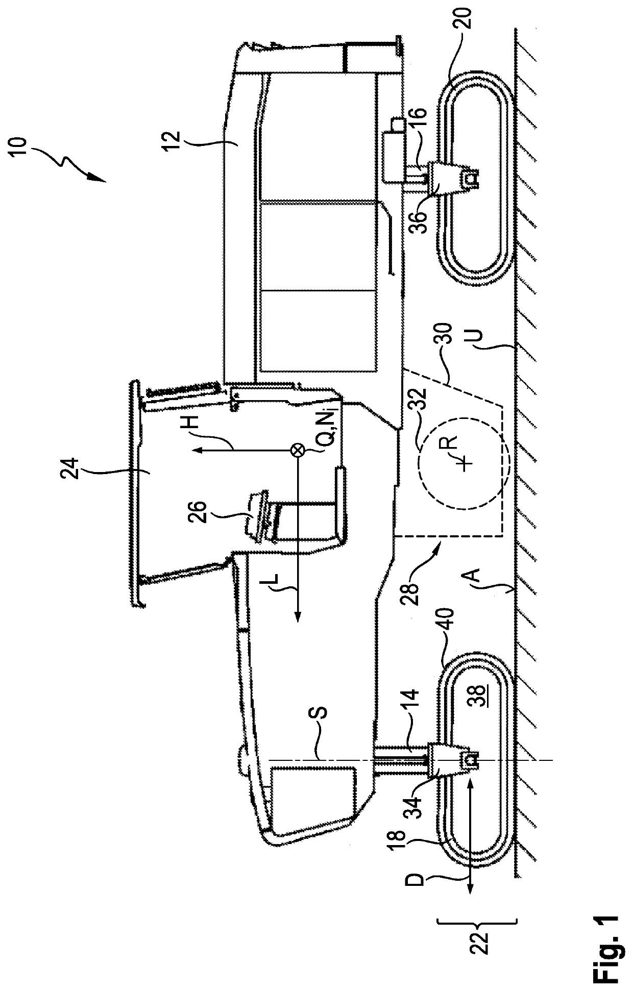
[0057]The viewer of FIG. 1 is looking toward earth moving machine 10, or simply the “machine,” in transverse machine direction Q that is orthogonal to the drawing plane of FIG. 1. The longitudinal machine frame direction is labeled L, and proceeds parallel to the drawing plane of FIG. 1. The vertical machine direction H also proceeds parallel to the drawing plane of FIG. 1, and orthogonally to the longitudinal and transverse machine directions L and Q. The arrowhead of longitudinal machine direction L in FIG. 1 points in a forward direction. For clarification, the vertical machine frame direction H is parallel to the direction in which lifting columns 14 and 16 proceed. Vertical machine direction H proceeds parallel to the yaw axis of machine 10, longitudinal machine direction L proceeds parallel to the roll axis, and transverse machine direction Q proceeds parallel to the pitch axis Ni.

[0058]Earth working machine 10 can comprise an operator's platform 24 from which a machine operat...


PUM


Abstract

A method for coupling a machine frame (12) of an earth working machine (10) to a working device (28) between the machine frame (12) and a substrate (U) encompasses the following steps:arranging the machine frame (12) and the working device (28) between the machine frame (12) and the substrate (U);aligning the receiving portion (42) and working device (28) relative to one another in such a way that fastening formations (56, 60) of the working device (28) are lined up, along a spacing direction, with fastening counter-formations (58, 62) of the machine frame (12);bringing the fastening formations (56, 60) and fastening counter-formations (58, 62) closer to one another; andoperably fastening the working device (28) onto the receiving portion (42).According to the present invention the aligning step encompasses the following sub-steps:connecting the machine frame (12) and the working device (28) to one another by means of a connecting apparatus (76), in such a way that the working device (28) is movable in response to its weight, parallel to the effective direction of gravity (g) and orthogonally thereto, relative to the machine frame (12); thenallowing the working device (28) to hang on the machine frame (12); and thensupporting the working device (28).

Description

BACKGROUND OF THE INVENTION1. Field of the Invention[0001]The present invention relates to a method for coupling a machine frame of an earth working machine, for example a road miller, stabilizer, or recycler, to a working device between a receiving portion of the machine frame which receives the working device and a substrate with which the earth working machine is in contact, the method encompassing the following steps:[0002]arranging the machine frame and the working device relative to one another in such a way that the working device is located between the machine frame and the substrate;[0003]aligning the receiving portion and working device relative to one another in such a way that fastening formations of the working device are lined up, along a spacing direction having a directional component orthogonal to the substrate, with fastening counter-formations, associated with the fastening formations and interacting for operable fastening of the working device onto the receiving ...

Claims


Application Information

Patent Timeline
Patent Type & Authority Applications(United States)
IPC IPC(8): E01C23/088E01C23/12
CPCE01C23/088E01C23/127E01C21/00
Inventor MANNEBACH, THOMASBARIMANI, CYRUSMENZENBACH, CHRISTOPH
Owner WIRTGEN GMBH
Learn More