
Passive RFID chip reader antenna and embedded RFID chips

a passive rfid chip and chip reader technology, applied in the field of passive rfid chip readers, can solve the problems of difficult or even impossible chip reading, higher cost of the process of embedding rfid chips in objects, and off-the-shelf” types of rfid chip readers, etc., to achieve optimally effective power transfer and data transfer

Inactive Publication Date: 2011-12-01
GELOWITZ CHRISTOPHER D +1
View PDF28 Cites 8 Cited by
  • Summary
  • Abstract
  • Description
  • Claims
  • Application Information

AI Technical Summary

Benefits of technology

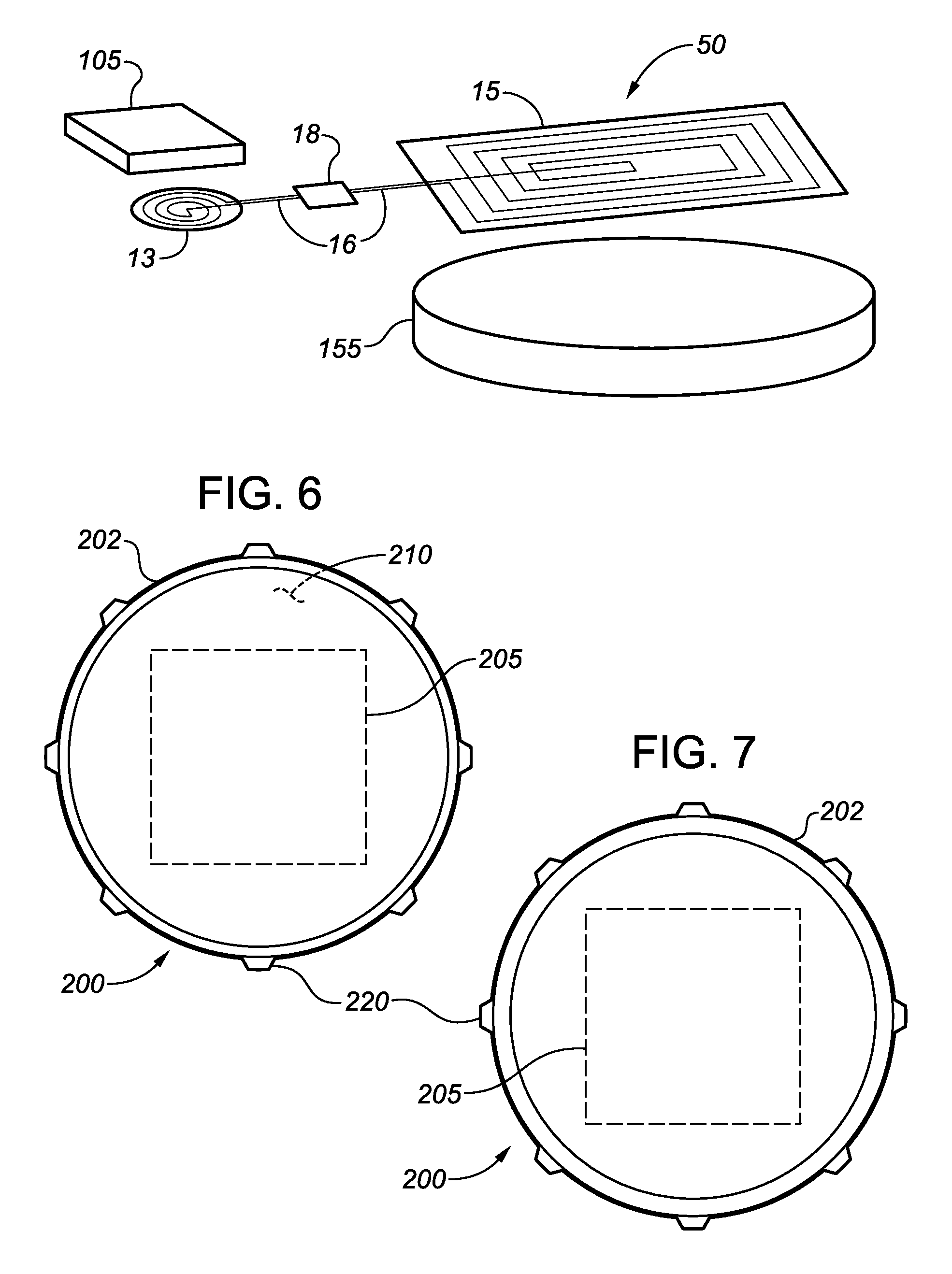
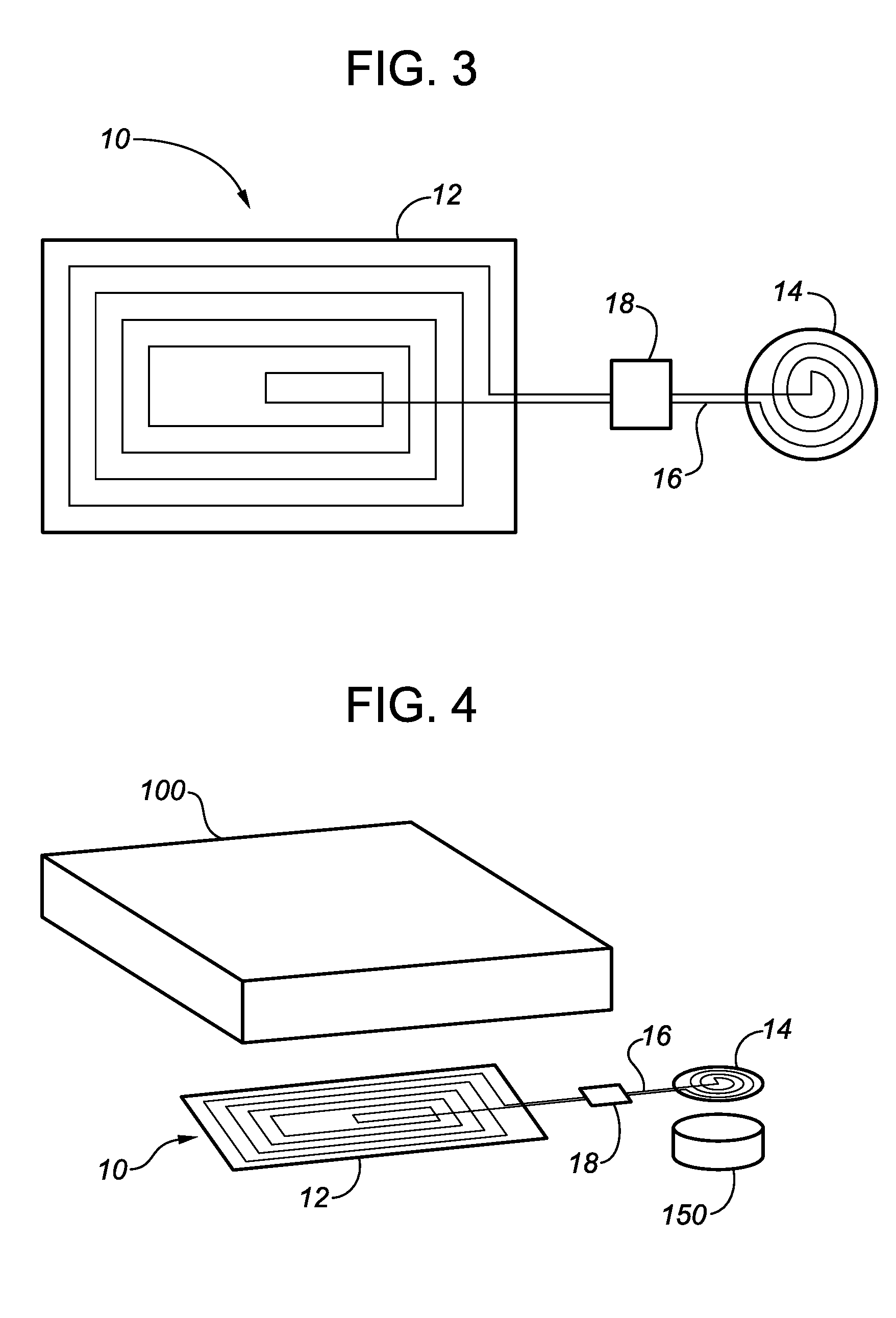
[0012]The present disclosure addresses the foregoing problems by teaching, in one aspect, an antenna apparatus for use in conjunction with a conventional RFID chip reader, or for incorporation into an as-manufactured RFID chip reader. The antenna apparatus in accordance with the present disclosure comprises a primary antenna and a remote antenna, spaced apart but in electrical communication with each other. In one embodiment, the remote antenna is smaller than the primary antenna. Preferably, but not necessarily, the physical size of the remote antenna is close to that of an RFID chip intended to be read with the antenna apparatus. This facilitates optimally-effective power transfer and data transfer between the RFID reader and the RFID chip, particularly in cases where the RFID chip is mounted to or embedded in an electrically-conductive metal object, which would create interference with radio frequency wave transmission between the RFID reader and the RFID chip.
[0015]RFID antenna apparatus in accordance with the present disclosure may be provided as a separate unit, thereby facilitating use with conventional RFID readers. In alternative embodiments, however, RFID antenna apparatus in accordance with the present disclosure may be incorporated into an RFID reader during initial manufacture.
[0017]In a second aspect, the present disclosure teaches an embedded or encapsulated RFID chip (alternatively referred to as an “RFID plug”) that can be securely and, for all practical purposes, permanently mounted or affixed to an object without use of adhesives, and without need for special tools. The RFID plug comprises an RFID chip encased within a preferably solid matrix of suitable plastic or other material that will not significantly impede or interfere with transmission of radio frequency signals, thus allowing the RFID chip to be read by an RFID chip reader even though the chip is encased. In illustrated embodiments, the RFID plug is of a disc-like cylindrical shape (somewhat suggestive of a tiny hockey puck), but having a plurality of rib-like ribs projecting radially outward from the cylindrical outer surface of the RFID plug. The shape and configuration of the ribs may vary in different embodiments of the RFID plug.

Problems solved by technology

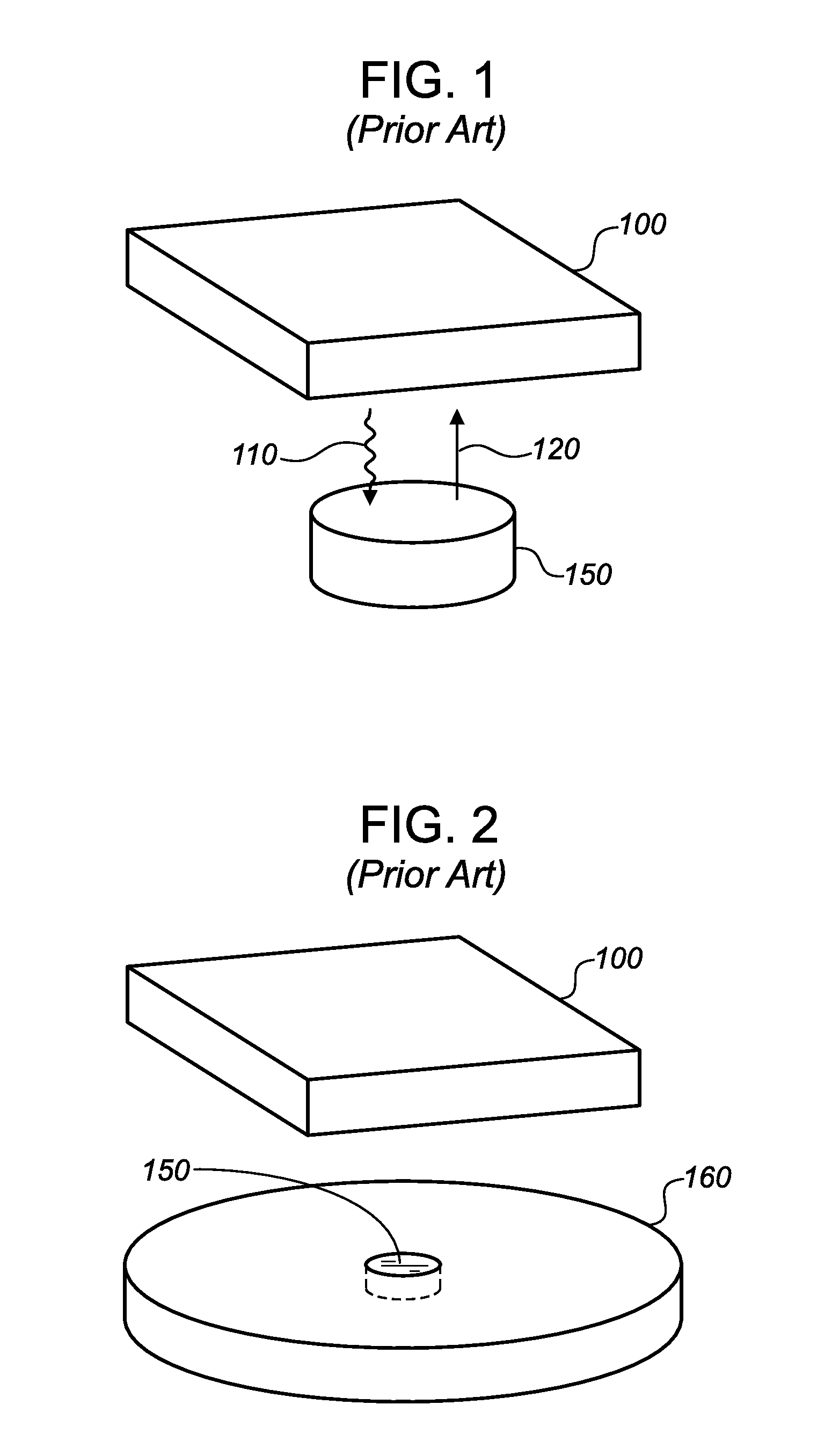
It has been found, for example, that if the receiving antenna of an RFID chip reader is quite large relative to the RFID chip antenna, or if the receiving antenna is small relative to the RFID chip, or if the RFID chip is embedded in a conductive metal such as steel or aluminum, the RF waves from the reader cannot energize the RFID chip, making it difficult or even impossible to read the chip.
These problems are common with known, “off-the-shelf” types of RFID chip readers.
This need to use adhesives results in higher costs for the process of embedding RFID chips in objects, as well as longer wait times before the objects in question are ready for use or shipping.
), but this design increases costs because of the larger chip-receiving pocket required and also the additional cost of handling two separate pieces.

Method used


Image

  • Passive RFID chip reader antenna and embedded RFID chips
  • Passive RFID chip reader antenna and embedded RFID chips
  • Passive RFID chip reader antenna and embedded RFID chips

Examples


first embodiment

[0052]FIGS. 6, 7, 8, and 9 are, respectively, top, bottom, isometric, and side views of an RFID plug 200 incorporating an RFID plug in accordance with the present teachings. FIGS. 10 and 10A are sectional and isometric views of RFID plug 200, shown in an initial position preparatory to effectively permanent installation in a plug-receiving pocket 255 formed in an object 250. In FIGS. 10 and 10A, object 250 is shown as a simple rectilinear block, but this is merely a convenient representational depiction; the actual configuration of an object 250 into which RFID plug 200 can be installed is for all practical purposes unrestricted.

[0053]In the embodiment shown in FIGS. 6-10 and 10A, RFID plug 200 and plug-receiving pocket 255 are of generally cylindrical configuration, with embedded RFID plug 200 comprising an RFID chip 205 embedded in a matrix 210 of non-electrically-conductive material such as but not necessarily limited to a plastic. RFID plug 200 incorporates a plurality of vertic...

embodiment 230

[0058]FIGS. 12 and 13 illustrate an alternative RFID plug embodiment 230, having radially-projecting ribs 232 with upper portions 234 and lower portions 236 separated by distinctly beveled transition sections 238. RFID plug 230 is thus largely similar to RFID plug 200 except that the beveled transition sections 238 of RFID plug 230 facilitate deformation of upper portions 234 of ribs 232 as RFID plug 230 is pressed into a plug-receiving pocket 255 in an object 250.

embodiment 240

[0059]FIGS. 14 and 15 illustrate another alternative RFID plug embodiment 240 of an RFID plug in accordance with the present disclosure. In this embodiment, each rib 242 of RFID plug 240 has an upper portion 244 which transitions to a comparatively steeply beveled lower portion 246 extending down to the bottom of RFID plug 240. The steeper bevel of lower portions 246 of RFID plug 240, thus facilitating deformation of upper portions 244 of ribs 242 as RFID plug 240 is press-fit into a plug-receiving pocket 255 in an object 250.

[0060]It will be appreciated that ribs 220, 232, and 242 in the illustrated RFID plug embodiments provide different features which can be beneficially advantageous for the purpose of installing RFID plugs into a plug-receiving pocket and effecting secure retention therein. In addition to their functional usefulness, ribs of the illustrated configurations can also be considered ornamental.

[0061]It will be appreciated by persons skilled in the art that RFID plugs...


PUM


Abstract

The present disclosure teaches an RFID chip reader comprising two spaced-apart antennae in electrical communication with each other, with one antenna being incorporated into the chip reader, and with the other antenna separate from the main body of the chip reader but in electrical communication with the other antenna by suitable circuitry. The RFID chip reader may optionally include tuner means disposed within the circuitry connecting the two antennae. One antenna may be smaller than the other to facilitate reading of data from an RFID chip associated with an object made from a electrically-conductive material. The chip reader may optionally incorporate tuner means associated with the circuitry connecting the antennas, to optimize circuitry effectiveness.Also taught is an RFID plug comprising an RFID chip encased within a non-conductive matrix, and having deformable projections to facilitate effectively permanent press-fit installation into a plug-receiving pocket in an object associated with the RFID chip.

Description

CROSS-REFERENCE TO RELATED APPLICATIONS[0001]This application claims the benefit of U.S. Provisional Application No. 61 / 348,575, filed on May 26, 2010, and said earlier application is incorporated herein by reference in its entirety for continuity of disclosure.FIELD OF THE DISCLOSURE[0002]The present disclosure relates in general to devices for reading passive RFID chips, and in particularly to devices for reading passive RFID chips that are embedded or encased in metallic articles. The disclosure further relates to RFID chips embedded or encapsulated in a protective matrix and adapted for insertion and secure retention within chip-receiving pockets in objects to be tracked with RFID technology, without requiring adhesives.BACKGROUND[0003]It is well known to use radio-frequency identification (RFID) chips (also called RFID tags) to identify and track objects. In simple terms, an RFID chip comprises an integrated circuit with a read-only memory (ROM), plus an antenna for receiving a...

Claims


Application Information

Patent Timeline
IPC IPC(8): H04Q5/22
CPCG06K19/07749G06K7/10178
Inventor GELOWITZ, CHRISTOPHER D.LEE, CHEN YUAN
Owner GELOWITZ CHRISTOPHER D
Learn More