
Steering drive for a motor vehicle

a technology for steering drives and motor vehicles, applied in electrical steering, synchronous machines with stationary armatures, rotating magnets, etc., can solve the problems of increased noise generation, high noise emissions of electric motors, and high operating speed required for boosting steering thrust, so as to reduce eddy current losses and reduce the detent torque of rotors

Active Publication Date: 2011-12-01
ROBERT BOSCH GMBH
View PDF2 Cites 17 Cited by
  • Summary
  • Abstract
  • Description
  • Claims
  • Application Information

AI Technical Summary

Benefits of technology

The aim of the present invention is to improve a steering drive in such a way that it is optimized for transferring a very high assistance torque at a simultaneous high level of efficiency while generating little noise in the driver's cab. At the same time, the steering drive can be cost-effectively manufactured.
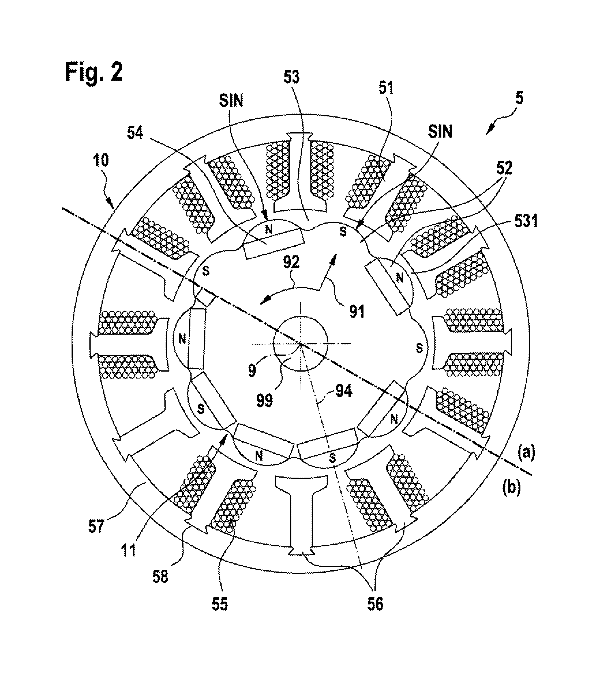
Because the electric motor interacts with the connecting rod according to the invention, the arrangement allows for the transfer of a large assistance torque. Due to the high level of efficiency of the belt drive, the on-board power supply system is loaded sufficiently low in this arrangement. At the same time, said electric motor is disposed in the engine compartment of the motor vehicle so that the noise level is low in the driver's cab even at high rpms. Furthermore, the noise level is reduced by the inventive use of an electric motor with twelve stator teeth and ten rotor poles embodied as sinus poles. This results from the fact that this design of the rotor poles causes a reduction in the harmonic content of the torques acting on the rotor.
A further advantage, which ensues from the sinus pole-shaped embodiment of the magnetic pole of the electric motor, is a significant reduction in the eddy current losses in the electric motor.
It is particularly preferred for a permanent magnet to be disposed in each rotor pole, the permanent magnets adjacent to one another being oppositely poled. It is likewise preferred for a permanent magnet to be disposed in every other rotor pole, the permanent magnets being of the same polarity. In the latter embodiment at least in the case of a magnetic field running radially, the opposite magnetic pole which in each case is oppositely positioned to the permanent magnet is formed by the yoke of the magnetic field through the material of the rotor so that a consequent-pole arrangement arises. The elimination of the permanent magnets is above all else cost efficient.
The rotor is preferably manufactured from one or a plurality of lamella packages in order to reduce eddy current losses. A plurality of lamella packages, which abut against each other and are tangentially offset relative to one another, is a particularly preferred embodiment. This tangential deviation of the lamella packages reduces the detent torque of the rotor.

Problems solved by technology

In the case of this arrangement, the operating speed required for boosting the steering thrust is however very high so that the noise emissions by said electric motor are also very high.
Furthermore, the tensile load on the shaft of the electric motor due to the belt is very large, which leads to a bowing of the rotor under load and causes additional noise generation.
Nevertheless, a large assistance torque like that required for steering drives in luxury-class vehicles is very difficult to transfer or cannot be transferred at all via the steering column.

Method used


Image

  • Steering drive for a motor vehicle
  • Steering drive for a motor vehicle
  • Steering drive for a motor vehicle

Examples


Embodiment Construction

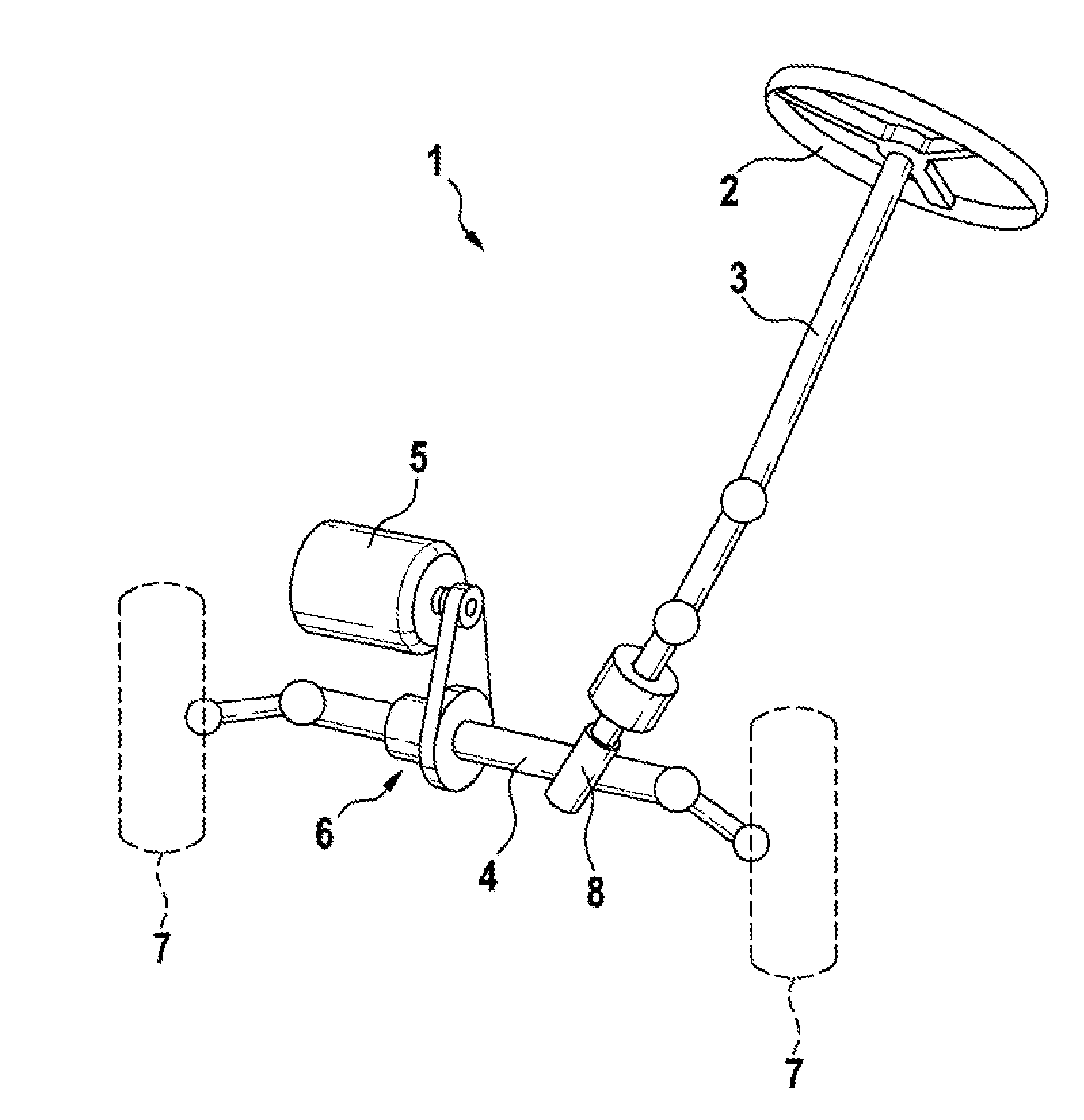
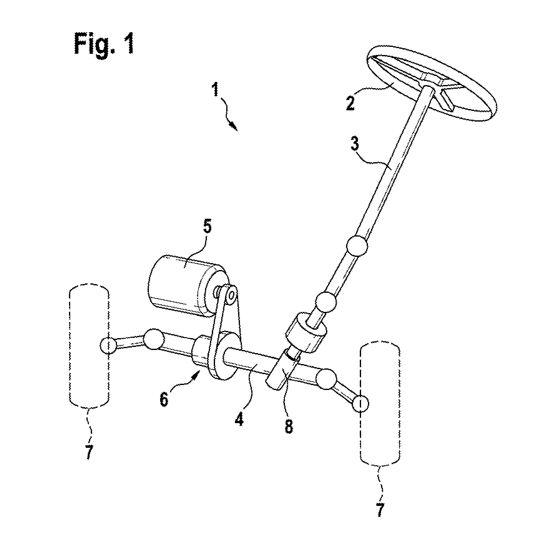
FIG. 1 schematically shows a steering drive 1 according to the invention. The steering drive 1 comprises a steering column 3, on which a steering wheel 2 is disposed for manipulation by a driver of the motor vehicle (not depicted). Said steering drive 1 furthermore comprises a connecting rod 4, which interacts with the steering column 3 by means of a gear assembly 8, particularly by means of a ball screw. In addition, said steering drive 1 comprises an electric motor 5, which interacts with the connecting rod 4 via a belt drive 6. The electric motor 5 is disposed in this instance substantially parallel to said connecting rod 4. The wheels 7 of the motor vehicle are additionally depicted here for the sake of clarification.

FIG. 2 schematically shows an embodiment of an electric motor 5 for the steering drive 1 according to the invention in a cross-sectional view. The depiction comprises a first embodiment of such an electric motor 5 in a first half (a) and a second embodiment of such ...


PUM


Abstract

A steering drive for a motor vehicle comprising a steering wheel, a steering column, on which the steering wheel is disposed, a connecting rod, which interacts with the steering column to deflect the wheels of the motor vehicle, an electric motor, which is provided for boosting the steering thrust, as well as a belt drive, the electric motor interacting with the connecting rod via the belt drive. Said electric motor comprises a stator having twelve stator teeth as well as a rotor having ten rotor poles, the rotor poles being spaced apart from each other by an air gap and embodied as sinus poles.

Description

BACKGROUND OF THE INVENTIONThe following invention relates to a steering drive for a motor vehicle for boosting the steering thrust, which comprises a belt drive.Steering drives, which support the handling of the steering wheel and simplify the vehicular steering for the driver are frequently used in motor vehicles. The German patent publication DE 10 2004 059 A1 reveals such a steering drive. In the case of this steering drive, the electric motor required for boosting the steering thrust is disposed parallel to the steering column of the steering drive in order to save installation space. The disposal of the electric motor laterally to the steering column is also known from prior art. This arrangement requires more installation space in comparison to the parallel arrangement.The electric motor of the aforementioned publication interacts with the steering column by means of a belt drive. In the case of this arrangement, the operating speed required for boosting the steering thrust i...

Claims


Application Information

Patent Timeline
IPC IPC(8): B62D5/04
CPCB62D5/0403B62D5/0424H02K2201/06H02K1/2773H02K21/16H02K1/276H02K1/2746
Inventor NEUBAUER, ACHIMPESCH, MICHAEL
Owner ROBERT BOSCH GMBH
Learn More