
Automated infection control surfaces

a technology of infection control and automatic surfaces, applied in the direction of lavatory sanitory, valve details, operating means/release devices of valves, etc., to achieve the effect of preventing operator exposur

Inactive Publication Date: 2011-11-24
ALLAN YANG WU
View PDF0 Cites 22 Cited by
  • Summary
  • Abstract
  • Description
  • Claims
  • Application Information

AI Technical Summary

Benefits of technology

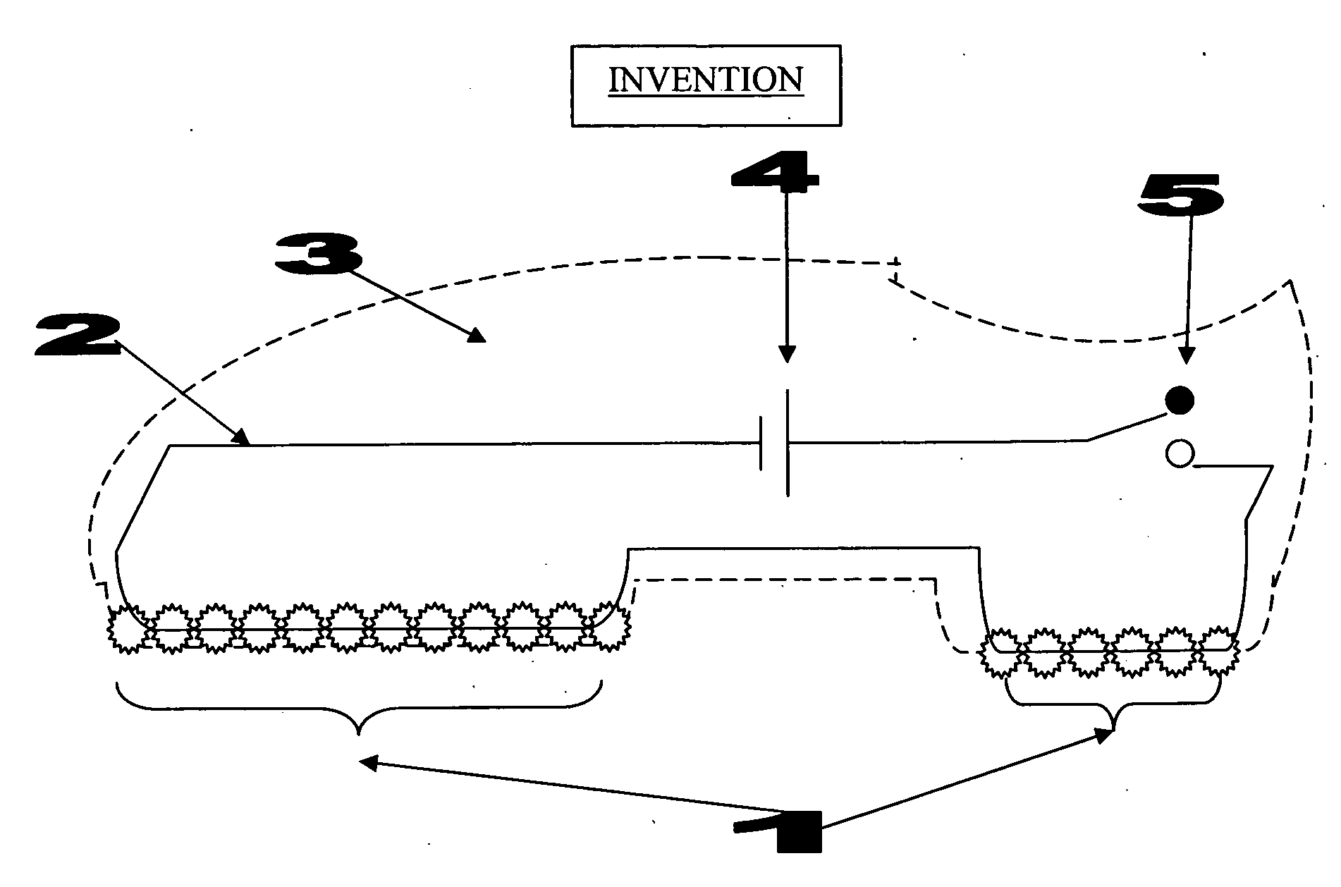
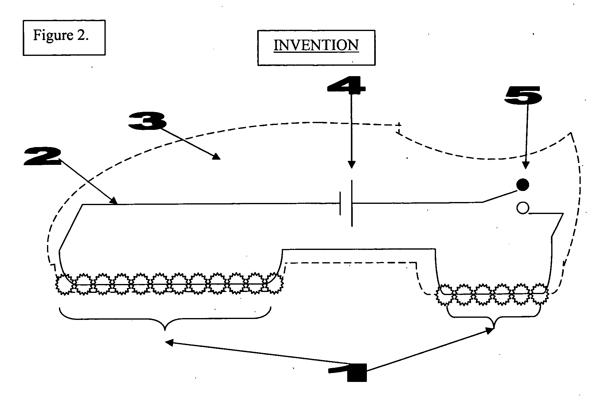
[0004]The invention is an infection control surface on the sole of a shoe, whereby the shoe is composed of a series of UV LEDs (light emitting diodes) on the sole of the shoe. Within the shoe itself is a pressure sensor that is triggered when the foot is planted within the shoe and standing firmly on the ground. When the pressure sensor is triggered the LEDs are turned on. When the shoe is lifted off the ground and when there is no weight or pressure within the shoe, the sensor is turned off and the LEDs turn off. In this way the shoe is only capable of triggering UV microbicidal activity when the sole is flush to the ground, thus preventing inadvertent UV light scatter and potential skin and eye damage.DISTINCTION FROM PRIOR ART

Problems solved by technology

In this way the shoe is only capable of triggering UV microbicidal activity when the sole is flush to the ground, thus preventing inadvertent UV light scatter and potential skin and eye damage.

Method used


Image

  • Automated infection control surfaces
  • Automated infection control surfaces
  • Automated infection control surfaces

Examples


Embodiment Construction

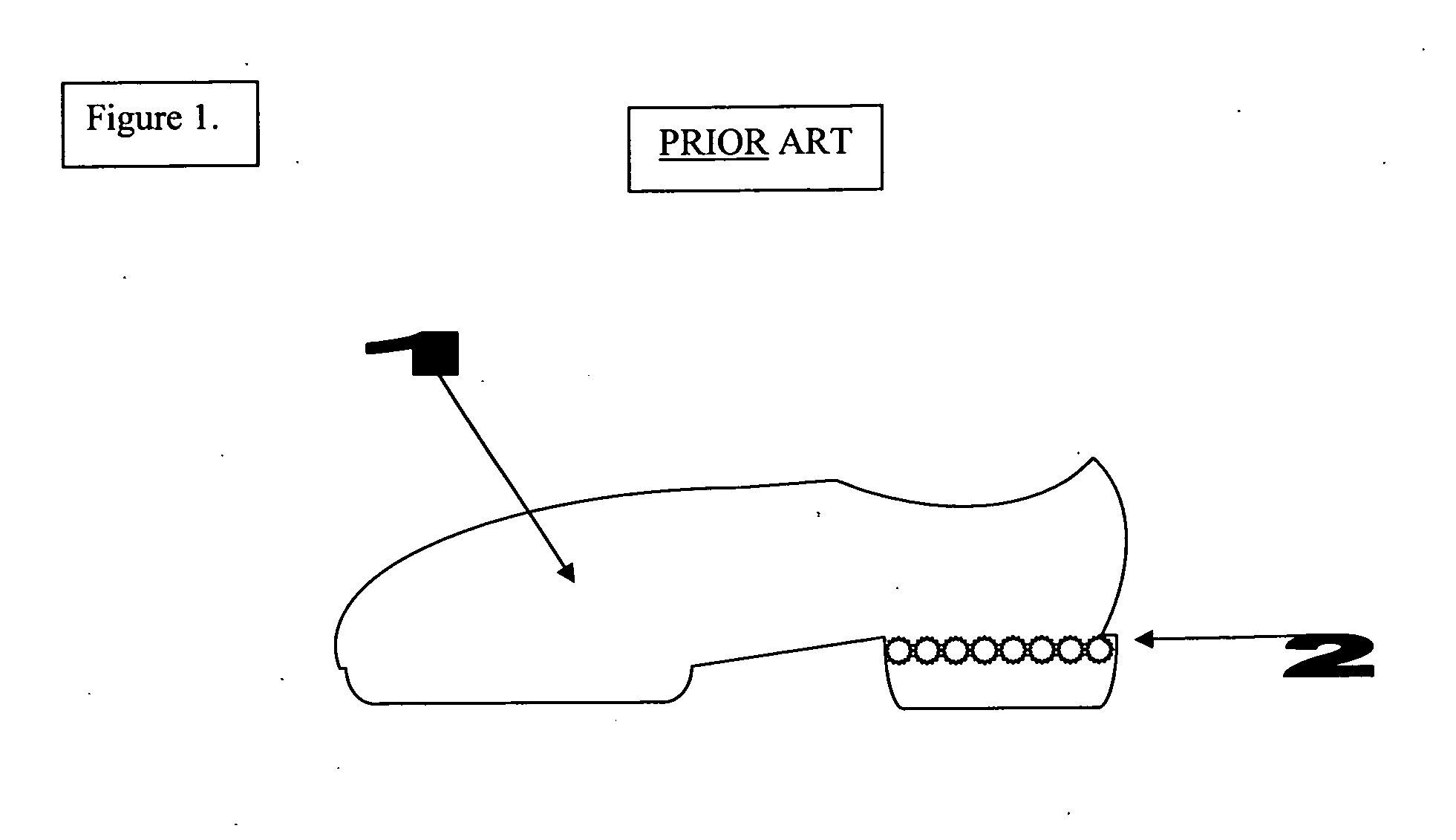
[0014]FIG. 1: Conceptual drawing of prior art. Such that a shoe (1) is illuminated by a light source or LEDs (2) in such a format that is visibly conspicuous to the naked eye.

[0015]FIG. 2: Conceptual drawing of invention, longitudinal cross-section. Such that the shoe (3) is composed of an internal circuit (2) connected to a power source (4), a weight sensitive switch (5), which when deployed illuminates lights / LEDs (1) connected to the circuit (2).

[0016]FIG. 3: Conceptual drawing of invention, in a bottom-up view; whereas the sole (1) of the shoe is covered with the light source / LEDs (2) and interspersed grips (3), represented by a series of interspersed parallel dotted lines, are used for traction.

[0017]FIG. 4: Conceptual drawing of alternate embodiment of invention, whereas the self-sterilizing touch sensitive surface is placed on a flooring tile or floor mat (1) and the light source or LEDs (2) are aimed upward toward the ceiling, but because invention illuminates in regions whe...


PUM

PropertyMeasurementUnit
weightaaaaaaaaaa
pressureaaaaaaaaaa
currentaaaaaaaaaa

Abstract

The invention is an automated infection control surface, which may be placed on the sole of a shoe or on the ground in the form of a floor mat / tile. The invention is composed of a series of individual light sources or LEDs (light emitting diodes) capable of emitting ultraviolet sanitizing light. When in the format of a shoe, there is an electronic switch in the form of a pressure sensor which is triggered when the operator's foot is planted within the shoe and standing firmly on the ground. When the pressure sensor is triggered the electrical current passes from the power source to the light sources or LEDs and illumination of sanitizing light occurs. When the shoe is lifted off the ground and when there is no weight or pressure within the shoe, the pressure sensor is turned off and the LEDs turn off. In this way the shoe is only capable of triggering UV microbicidal activity when the sole is flush to the ground, thus preventing inadvertent UV light scatter and potential skin and eye damage. The invention may also be composed in an array like fashion in the form of a floor mat or tile, such that the LEDs are oriented upwardly to shine towards the sole of the operator's shoe, but always concealed underneath the shoe. In either embodiment the LEDs are turned off when there is no weight on the sole of the shoe or floor mat / tile. Both embodiments of the invention could also be used simultaneously to provide maximum sterilization activity.

Description

BACKGROUND OF THE INVENTION[0001]PATENTS CITED:Patent NumberTitleIssue date5,500,635Products incorporating Mar. 19, 1996piezoelectric material6,280,045Lighted footwear module Aug. 28, 2001with random time delay5,978,996Shoe tree assemblyNov. 9, 1999[0002]Shoes and flooring sanitation present some of the greatest challenges to infection control. Cleaning floors with a mop along with peroxide, bleach or various detergents is a common means of minimizing the spread of contamination. Shoe covers are also another means of preventing contamination spread. Though both methods are successful current standards of sanitation, both require strict compliance, which can be difficult to obtain in practice, especially in a busy occupational environment.[0003]Another potential solution to this problem is use of ultraviolet light. Antimicrobial lamps utilizing wavelengths in the ultraviolet (UV) spectrum are capable of inducing DNA single strand breaks. For this reason UV light has been used as a co...

Claims


Application Information

Patent Timeline
Patent Type & Authority Applications(United States)
IPC IPC(8): A61L2/08A61L2/24
CPCA61L2/10A61L2202/25A61L2202/14
Inventor WU, ALLAN YANG
Owner ALLAN YANG WU
Learn More