Image printing apparatus, image printing method, and storage medium
a technology of image printing and image, applied in the direction of digital output to print units, digitally marking record carriers, instruments, etc., can solve the problems of inability to adjust the rotation speed of the polygon mirror to the sub-scanning direction, the extension of the sub-scanning direction is undesired, and the paper subject to heat and pressure is undesired
- Summary
- Abstract
- Description
- Claims
- Application Information
AI Technical Summary
Benefits of technology
Problems solved by technology
Method used
Image
Examples
embodiment 1
[0032]FIG. 1 illustrates an example of the configuration of an image printing apparatus according to Embodiment 1. Although FIG. 1 shows an image printing apparatus based on the electrophotographic method, the present invention is not limited to this. The Embodiment 1 is also applicable to image printing apparatuses based on any printing method that causes the extension of a recording medium such as a paper due to the printing of the recording medium. Furthermore, the recording medium is not limited to a paper and may be any medium that is extended when being subjected to printing.
[0033]The reference numeral 100 denotes a printing mechanism that includes an optical scanning drawing mechanism 101, a photoconductive drum 102, and a fixing mechanism 103. Arrows in the printing mechanism 100 show paper feeding paths. The reference numeral 110 denotes a normal (front side) feeding path and the reference numeral 111 denotes a back side feeding path, respectively. The printing mechanism 10...
embodiment 2
[0084]In Embodiment 1, the correction coefficient was calculated based on the paper extension and shrink rate inputted by the user through the user interface 301. The following section will describe an embodiment as Embodiment 2 where the correction coefficient is automatically calculated using the paper detection sensor 104 provided in the normal feeding path 110.
[0085]As can be seen from FIG. 1, the paper detection sensor 104 exists between the meeting point of the back side feeding path 111 after the switchback mechanism 112 and the normal feeding path 110 and the photoconductive drum 102 for transferring a toner image. This paper detection sensor 104 is used to measure the time required to print a front side of a paper and the time required to print the back side to thereby automatically calculate the correction coefficient.
[0086]FIG. 6 is a flowchart illustrating the flow of the processing for automatically calculating a correction coefficient.
[0087]In Step 601, upon receiving ...
embodiment 3
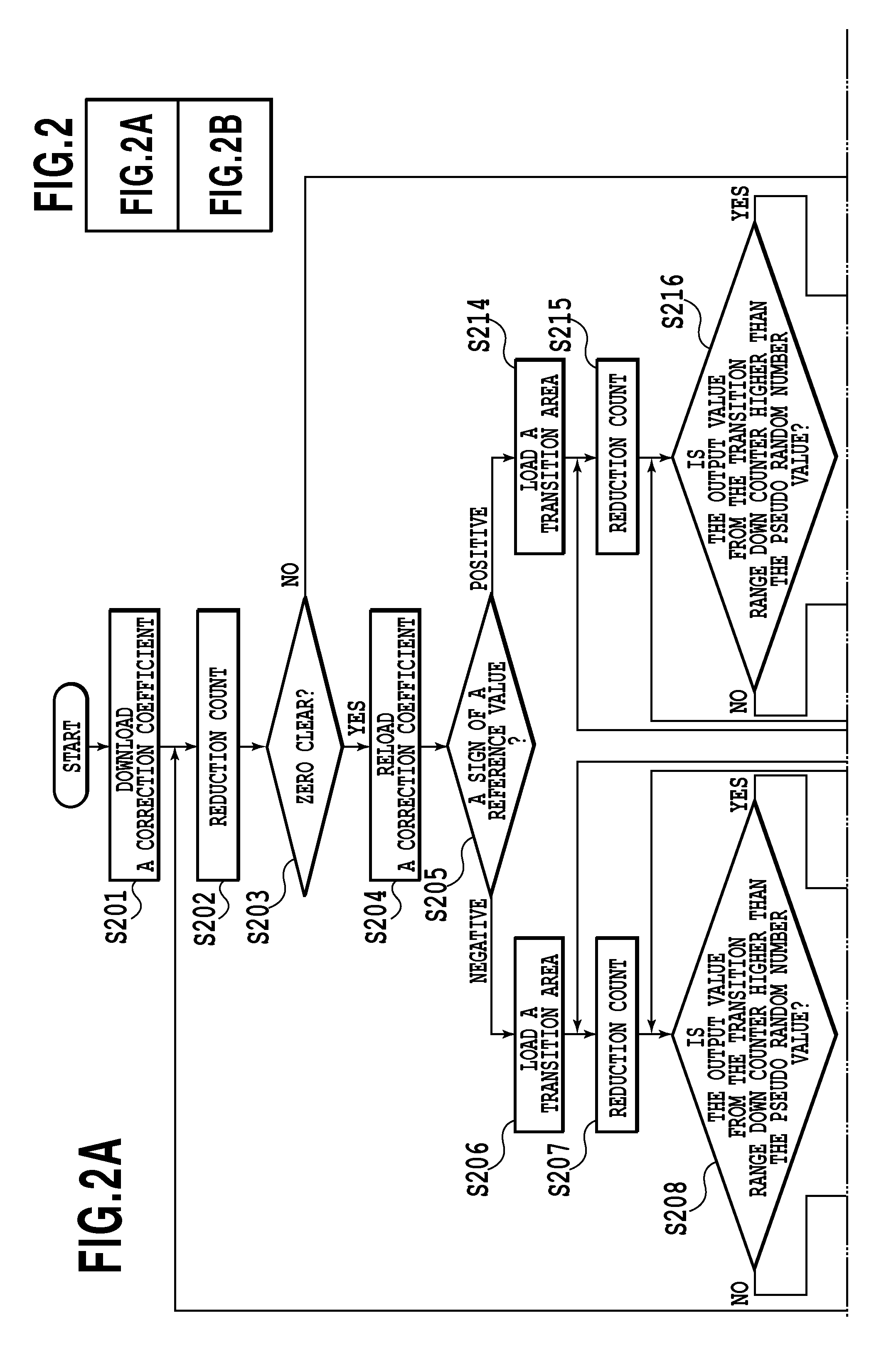
[0104]Some printing mechanisms realize the formation of an image by superimposing a plurality of drawings and scannings because single drawing and scanning provide an insufficient printing concentration in the resultant output. Another printing mechanism equalizes drawing positions by a multi scanning because a printing density exceeding 1000 dpi causes a pixel size to be smaller than 25.4 μm to cause an undesired exchange of pixel drawing positions depending on a paper position accuracy. As described above, in the case where an image is formed on a paper by a multi drawing and scanning, a difference in the size is also undesirably caused between an image formed by the first drawing and scanning and an image formed by drawings and scannings after the second drawing and scanning. Thus, a processing is required to correct the image size. When the same side of a paper is subjected to a plurality of drawings and scannings, a visually-favorable result can be obtained by using transition ...
PUM
 Abstract
Description
Claims
Application Information
 - R&D
- Intellectual Property
- Life Sciences
- Materials
- Tech Scout
- Unparalleled Data Quality
- Higher Quality Content
- 60% Fewer Hallucinations
Browse by: Latest US Patents, China's latest patents, Technical Efficacy Thesaurus, Application Domain, Technology Topic, Popular Technical Reports.
© 2025 PatSnap. All rights reserved.Legal|Privacy policy|Modern Slavery Act Transparency Statement|Sitemap|About US| Contact US: help@patsnap.com


