Quinoxaline Derivative, and Light-Emitting Element, Light-Emitting Device, and Electronic Device Using the Same
a technology of quinoxaline derivative and light-emitting element, which is applied in the direction of thermoelectric devices, other domestic articles, organic chemistry, etc., can solve the problems of affecting the efficiency of light-emitting elements, affecting the display quality of light-emitting elements, and changing the emission spectrum, so as to improve the display quality and the effect of excellent electron-transporting properties and reducing power consumption of such electronic devices
- Summary
- Abstract
- Description
- Claims
- Application Information
AI Technical Summary
Benefits of technology
Problems solved by technology
Method used
Image
Examples
embodiment mode 1
Hereinafter, a quinoxaline derivative of the present invention is described. The quinoxaline derivative of the present invention is a quinoxaline derivative represented by the general formula (G1) below.
In the formula, α1 and α2 each independently represent an arylene group which has 13 or less carbon atoms forming a ring, for example, a divalent group derived from benzene, naphthalene, fluorene, or the like. Such a group may, but not necessarily, have a substituent. If the group has a substituent, an alkyl group having 1 to 6 carbon atoms, a phenyl group, or the like can be used.
Further, in the formula, Ar represents an aryl group which has 13 or less carbon atoms forming a ring. Specifically, a phenyl group, a biphenyl group, a naphthyl group, a fluorenyl group, and the like can be given. Such a group may have a substituent. If the group has a substituent, the group has an alkyl group having 1 to 6 carbon atoms, a phenyl group, a biphenyl group, or the like. These substituents may...
embodiment mode 2
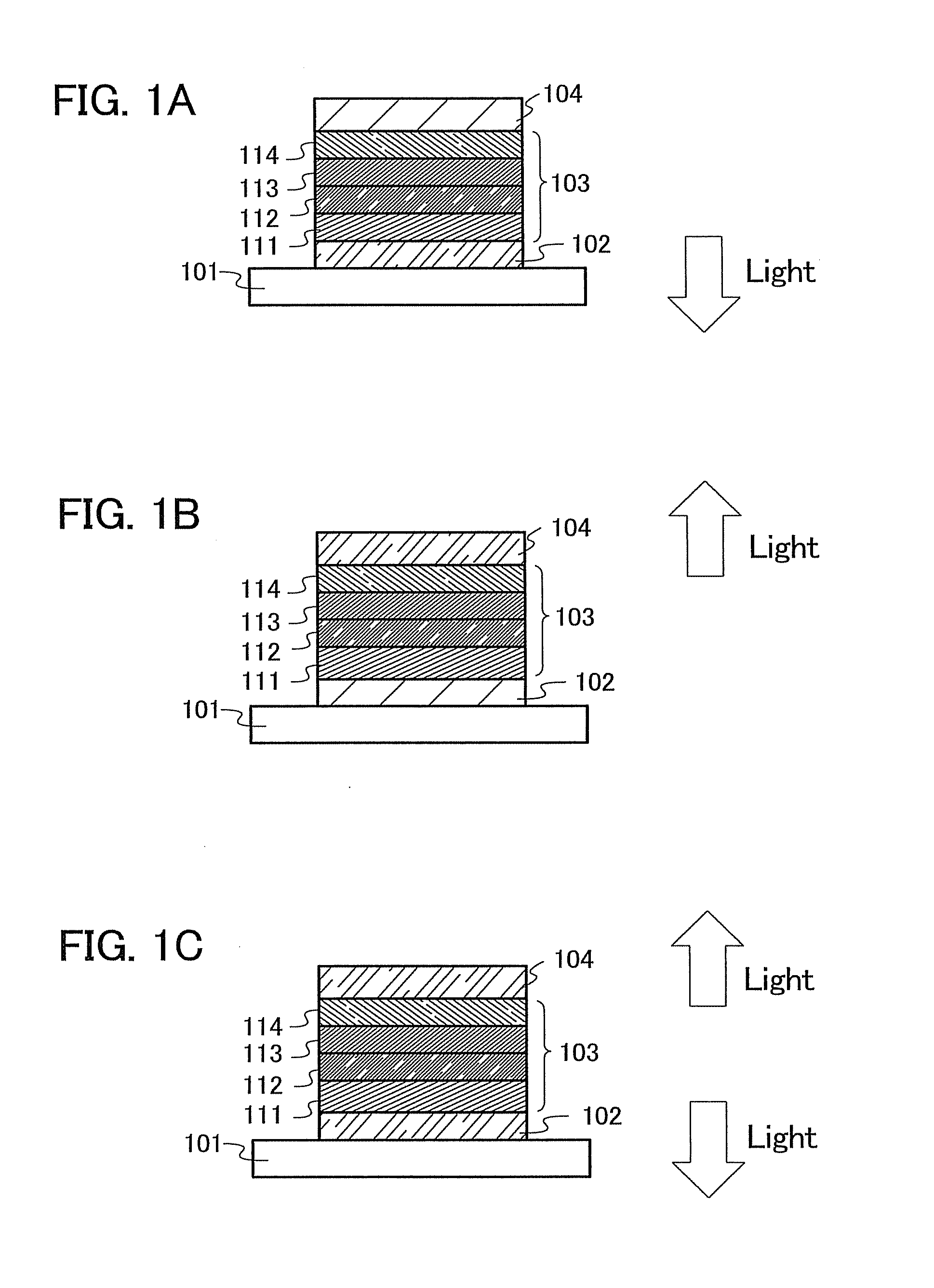
Hereinafter, a mode of a light-emitting element using the quinoxaline derivative of the present invention is described using FIG. 1A.
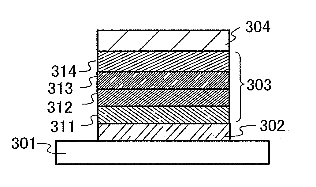
A light-emitting element of the present invention has a plurality of layers between a pair of electrodes. In this embodiment mode, the light-emitting element includes a first electrode 102, a second electrode 104, and an EL layer 103 provided between the first electrode 102 and the second electrode 104. Note that in this embodiment mode, the first electrode 102 serves as an anode and that the second electrode 104 serves as a cathode. In other words, hereinafter, it is assumed that when a voltage is applied to the first electrode 102 and the second electrode 104 so that the potential of the first electrode 102 is higher than that of the second electrode 104, light emission can be obtained.
A substrate 101 is used as a support of the light-emitting element. For example, glass, plastic, or the like can be used for the substrate 101. Any material other than...
embodiment mode 3
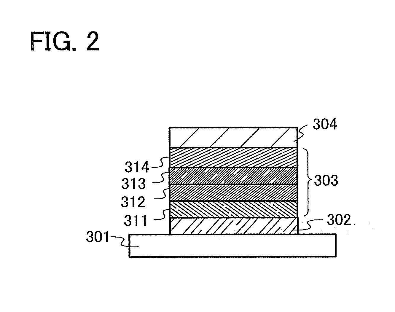
In this embodiment mode, a light-emitting element having a structure different from the structure described in Embodiment Mode 2 is described.
The light-emitting layer 113 described in Embodiment Mode 2 contains the quinoxaline derivative of the present invention, which is dispersed in another substance; accordingly, light emission can be obtained from this quinoxaline derivative of the present invention. Since the quinoxaline derivative of the present invention exhibits emission of blue to green light, a blue to green light-emitting element can be obtained.
Here, as the substance in which the quinoxaline derivative of the present invention is dispersed, instead of the substance having a high hole-transporting property or the substance having a high electron-transporting property, which is described in Embodiment Mode 2, any of a variety of materials such as 4,4′-di(N-carbazolyl)biphenyl (abbreviation: CBP); 2,2′,2″-(1,3,5-benzenetriyl)tris(1-phenyl-1H-benzimidazole) (abbreviation: TP...
PUM
| Property | Measurement | Unit |
|---|---|---|
| work function | aaaaa | aaaaa |
| work function | aaaaa | aaaaa |
| fluorescence | aaaaa | aaaaa |
Abstract
Description
Claims
Application Information
 - R&D
- Intellectual Property
- Life Sciences
- Materials
- Tech Scout
- Unparalleled Data Quality
- Higher Quality Content
- 60% Fewer Hallucinations
Browse by: Latest US Patents, China's latest patents, Technical Efficacy Thesaurus, Application Domain, Technology Topic, Popular Technical Reports.
© 2025 PatSnap. All rights reserved.Legal|Privacy policy|Modern Slavery Act Transparency Statement|Sitemap|About US| Contact US: help@patsnap.com


