
Ceramic lag bolt and use thereof in high temperature insulation installation

a technology of lag bolts and lag bolts, which is applied in the direction of threaded fasteners, furnaces, lighting and heating apparatus, etc., can solve the problems of limiting the maximum temperature of the system, the type and type of pins are usually detelinined by the overall cost associated with a particular furnace implementation, and the use of more costly insulating materials and anchoring systems to withstand extreme temperatures, so as to achieve time-saving and cost-effective maintenance of the interior of the furna

Inactive Publication Date: 2011-11-24
STELLAR MATERIALS
View PDF4 Cites 2 Cited by
  • Summary
  • Abstract
  • Description
  • Claims
  • Application Information

AI Technical Summary

Benefits of technology

The present invention provides a high temperature resistant anchor for securing high temperature insulation to low temperature insulation materials in enclosed heating areas such as kilns, furnaces, and process heating equipment. The anchor is made of ceramic and can be easily inserted into the insulation materials using a screw. The invention combines the benefits of the "wallpaper" system and the module system, resulting in a lower cost and more thermally efficient lining with broken or staggered seams to combat the flow of heat. The invention also includes a method for replacing damaged portions of the insulation and a method for securing a heating element to the interior insulation of a furnace. The technical effects of the invention include improved durability, reliability, and repairability of the lining materials, as well as cost-effective and efficient maintenance of the interior of the furnace.

Problems solved by technology

The alloy of the metallic pin will vary depending on the furnace temperature, however, most all layered blanket systems are limited to a maximum temperature of <2150° F. since this is the upper use limit of conventional alloys currently being employed.
The type and kind of material used for the pins is usually detelinined by the overall cost associated with a particular furnace implementation, including the insulation and the operating temperature of the furnace.
As a general rule, when the process temperatures increase, more costly insulating materials and anchoring systems must be employed to withstand the extreme temperatures and corrosive conditions associated in such environments.
Both the end of the pin and securing clip are directly exposed to furnace temperatures, thus greatly limiting the maximum temperatures where this system can be used.
While different in composition, both the metallic or ceramic pins originate at the steel casing, require a pre-layout to install, and are extremely difficult, if not impossible to repair if damaged.
In addition, as temperatures increase, the cost of the pins will increase as well as better alloys or ceramics must be used to survive the high temperatures found in various furnaces, kilns, or heaters.
This is a result of the lining materials being perpendicular to the flow of heat and that the layered blanket system permits the seams of each layer to be staggered or broken so there can never be a direct path of heat to the furnace casing.
This inability to use lower temperature, less costly insulation at the cooler depths of the lining thickness results in costs which can be significantly higher (e.g., 23 times higher) than “wallpaper” systems.
In addition, the insulation of a module system is predominantly oriented parallel to the heat path, thus making it less efficient than “wallpaper” systems.
Further, since there are no staggered layers in a module lining, there is a potential for a direct heat path to the furnace casing surrounding each module should the lining be compromised by mechanical damage, chemical attack, and / or heat related shrinkage.
These mortared-on veneering modules frequently fall off due to differences in expansion at the mortar joint, poor bonding, or improper installation.
In the case of full thickness module linings, there is a straight through joint surrounding every module that may provide a direct path for heat, should the module experience heat-related shrinkage, mechanical damage, or poor installation practices.

Method used


Image

  • Ceramic lag bolt and use thereof in high temperature insulation installation
  • Ceramic lag bolt and use thereof in high temperature insulation installation
  • Ceramic lag bolt and use thereof in high temperature insulation installation

Examples


Embodiment Construction

[0028]The present invention will now be described with reference to the accompanying figures. It is to be understood that the specific system and applications illustrated in the attached figures and described in the following specification are simply exemplary embodiments of the present invention. Hence, specific dimensions and other physical characteristics related to the embodiments disclosed herein are not to be considered as limiting.

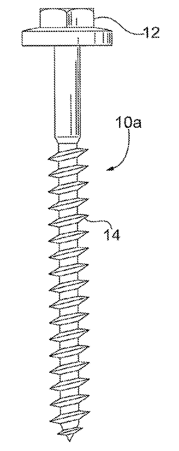
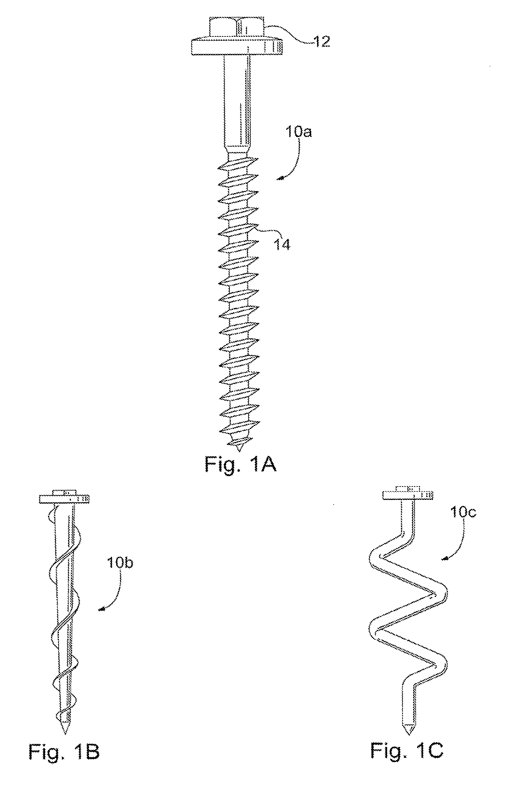
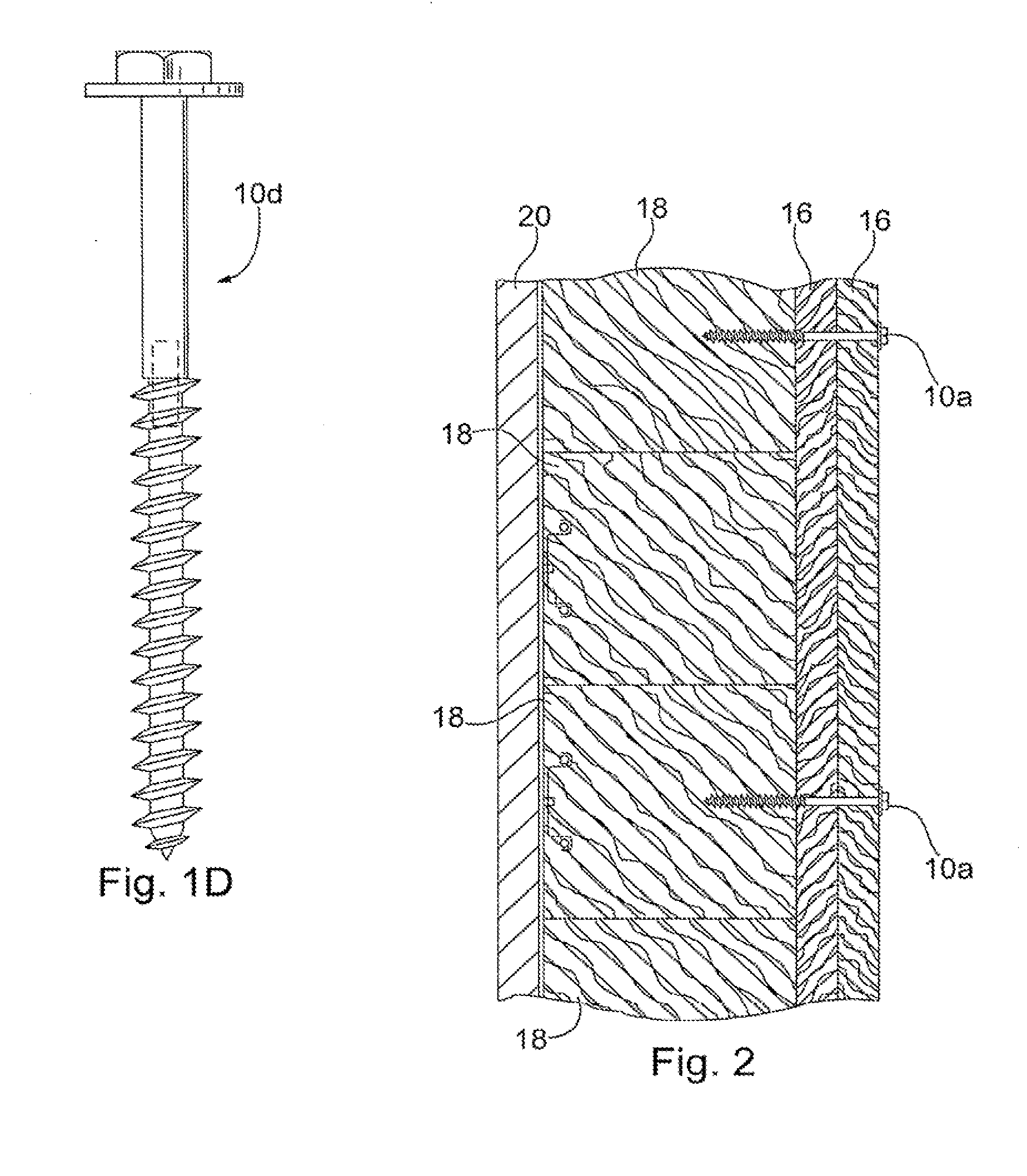
[0029]FIG. 1a depicts an anchor, embodied as a ceramic lag bolt 10a. In a desirable embodiment, the ceramic lag bolt 10a includes a drive head 12 and a shank 14. In one embodiment, the ceramic lag bolt 10a may be 8″ to 10″ in length. The ceramic material is such that it can withstand high temperatures within a furnace, kiln, or other high temperature environment. One exemplary ceramic material may be any non-metallic, inorganic, burnt material, however, it is to be understood that other suitable materials may be utilized. The drive head 12 may be of...


PUM

PropertyMeasurementUnit
temperatureaaaaaaaaaa
densityaaaaaaaaaa
densityaaaaaaaaaa

Abstract

A method for securing a hot face insulation to a cold face insulation of an enclosed heating area includes (a) providing a first insulating material having a first and second side; (b) providing a second insulating material having a first and second side, wherein the second insulating material provides for higher temperature insulation than the first insulating material, wherein the first side of the first insulating material is positioned against and secured to the interior surface of the enclosed heating area; (c) positioning the second insulating material against the first insulating material so that the first side of the second insulating material abuts the second side of the first insulating material; (d) providing an auger bolt as an anchor; and (e) inserting the auger bolt into the second side of the second insulating material, through the second insulating material, and into the second side of the first insulating material.

Description

CROSS REFERENCE TO RELATED APPLICATIONS[0001]This application claims the benefit of U.S. Provisional Patent Application No. 61 / 013,875 filed Dec. 14, 2007, and entitled “Ceramic Lag Bolt and Use Thereof in High-Temperature Insulation Installation,” the contents of which are incorporated herein by reference. This application is a divisional of 12 / 335,303, filed on Dec. 15, 2008.BACKGROUND OF THE INVENTION[0002]1. Field of the Invention[0003]The present invention relates to a system and method for securing insulation to an enclosed heating area, such as a furnace or kiln and, more particularly, to a system and method for securing high temperature insulating material to a low temperature insulating material that is secured to an interior surface of such furnace or kiln.[0004]2. Description of Related Art[0005]The walls of a furnace, kiln, hot duct, or the like, are usually lined with ceramic fiber boards, blankets, insulating fire brick (IFB), and / or ceramic fiber modules for insulatio...

Claims


Application Information

Patent Timeline
Patent Type & Authority Applications(United States)
IPC IPC(8): B23P11/00
CPCF16B33/006F27D1/0006Y10T29/49947F27D1/144F27D1/0009
Inventor PERRY, MATTHEW L.
Owner STELLAR MATERIALS
Learn More