
Heat dissipation structure for liquid crystal television

Inactive Publication Date: 2011-11-17
SILICON INTEGRATED SYSTEMS
View PDF11 Cites 5 Cited by
  • Summary
  • Abstract
  • Description
  • Claims
  • Application Information

AI Technical Summary

Benefits of technology

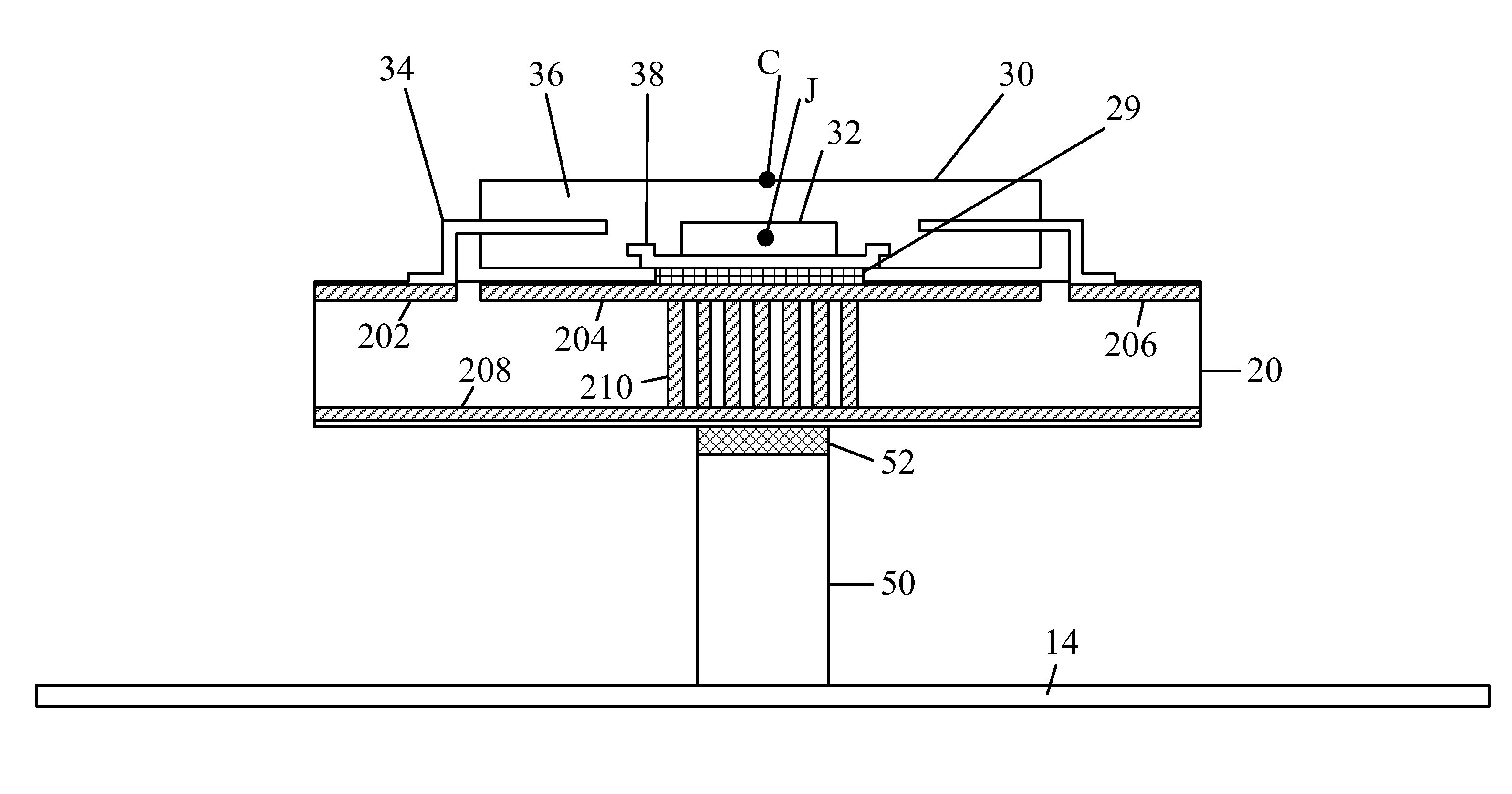
[0008]An objective of the present invention is to provide a heat dissipation structure for a liquid crystal television. The liquid crystal television includes a front plate and a rear plate. The front plate has a screen installed at a front side and a metal backboard mounted at a back side thereof. The front plate and the rear plate are assembled to form the liquid crystal television. By using the heat dissipation structure, the heat generated by the television IC chip can be effectively dispersed with a low cost.

Problems solved by technology

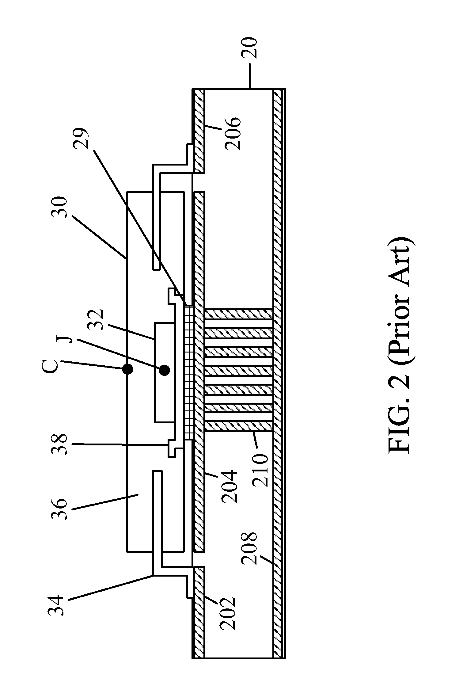
However, such PCBs have poor heat dispersing performance.
Accordingly, heat dispersion for the television IC chip 30 is poor.
Once the television IC chip 30 is overheated, it may operate abnormally.
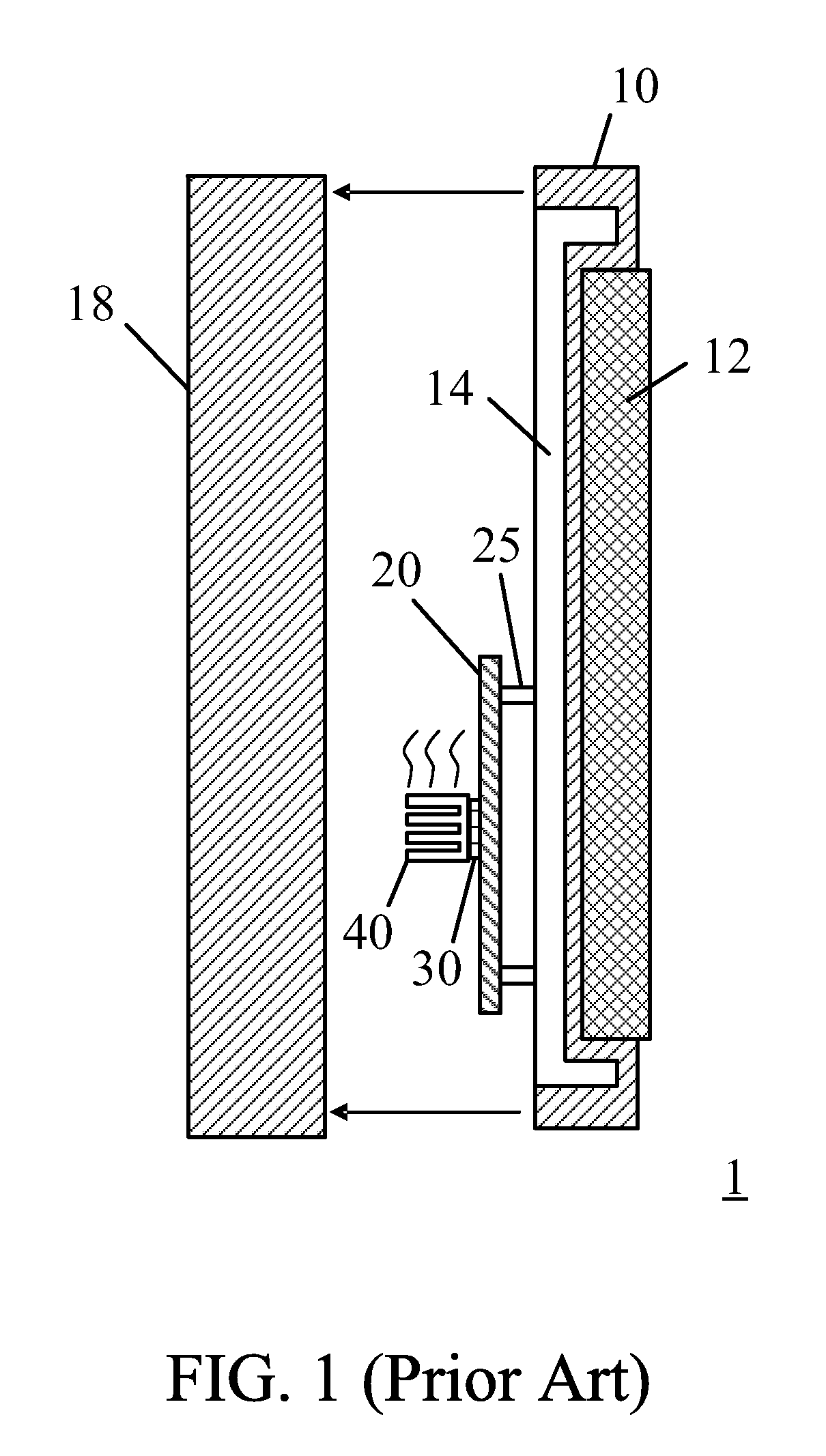
However, the heat sink 40 with multiple fins is thick and occupies a considerable space, and thereby hindering the liquid crystal television 1 from being further thinned.
In addition, the heat sink 40 is expensive.

Method used


Image

  • Heat dissipation structure for liquid crystal television
  • Heat dissipation structure for liquid crystal television
  • Heat dissipation structure for liquid crystal television

Examples


Embodiment Construction

[0018]FIG. 4 is a schematic diagram showing a heat dissipation structure in accordance with an embodiment of the present invention. FIG. 5 is a schematic diagram showing a section view of a liquid crystal television 2 provided with the heat dissipation structure of FIG. 4. The same reference numbers of these drawing and other drawings indicate the same components, and the relevant descriptions will be omitted to avoid repetition and redundancy.

[0019]Similar to FIGS. 1-3, an EP-LQFP type of television IC chip 20 is disposed on a PCB 20. The PCB 20 is mounted on a metal backboard 14 of a front plate 10 of the liquid crystal television 2 by means of pillars 25. In the present invention, no convention heat sink is used. As shown, a heat dissipating post 50 is provided between the PCB 20 and the metal backboard 14. The dissipating post 50 is made of heat conductive material such as metal (e.g. aluminum). The position where the dissipating post 50 is located is corresponding to the televi...


PUM


Abstract

A heat dissipation structure for a liquid crystal television is disclosed. The liquid crystal television includes a front plate and a rear plate. The front plate has a screen and a metal backboard. The heat dissipation structure includes a printed circuit board (PCB) mounted to the metal backboard; a television integrated circuit (IC) chip for controlling operations of the liquid crystal television being attached on the PCB; and one or more heat dissipating posts provided between the PCB and the metal backboard. The heat generated by the television IC chip is dispersed to the metal backboard via the heat dissipating post or posts.

Description

TECHNICAL FIELD OF THE INVENTION[0001]The present invention relates to heat dissipation, more particularly, to a heat dissipation structure for a liquid crystal television.BACKGROUND OF THE INVENTION[0002]In a low price liquid crystal television, printed circuit broads (PCBs) are implemented with PCBs having only two copper sheets to reduce the cost. However, such PCBs have poor heat dispersing performance. In order to maintain a television IC (integrated circuit) chip operating normally, a heat sink is usually used to disperse the heat from the television IC chip.[0003]FIG. 1 is a schematic diagram showing a sectional view of a general liquid crystal television 1 with a conventional heat sink 40. As shown, the liquid crystal television 1 includes a front plate 10 having a television screen 12 mounted on a front side thereof and a metal backboard 14 mounted on a rear side thereof. The liquid crystal television 1 further includes a rear plate 18, which is assembled with the front pla...

Claims


Application Information

Patent Timeline
IPC IPC(8): H05K7/20
CPCH05K7/20963H04N5/64
Inventor TSAI, TSAI-CHIHJIAN, JHIH-JHONGHSUEH, YIN-CHIEH
Owner SILICON INTEGRATED SYSTEMS
Learn More