
Cloth treating apparatus

Inactive Publication Date: 2011-11-17
LG ELECTRONICS INC
View PDF11 Cites 80 Cited by
  • Summary
  • Abstract
  • Description
  • Claims
  • Application Information

AI Technical Summary

Benefits of technology

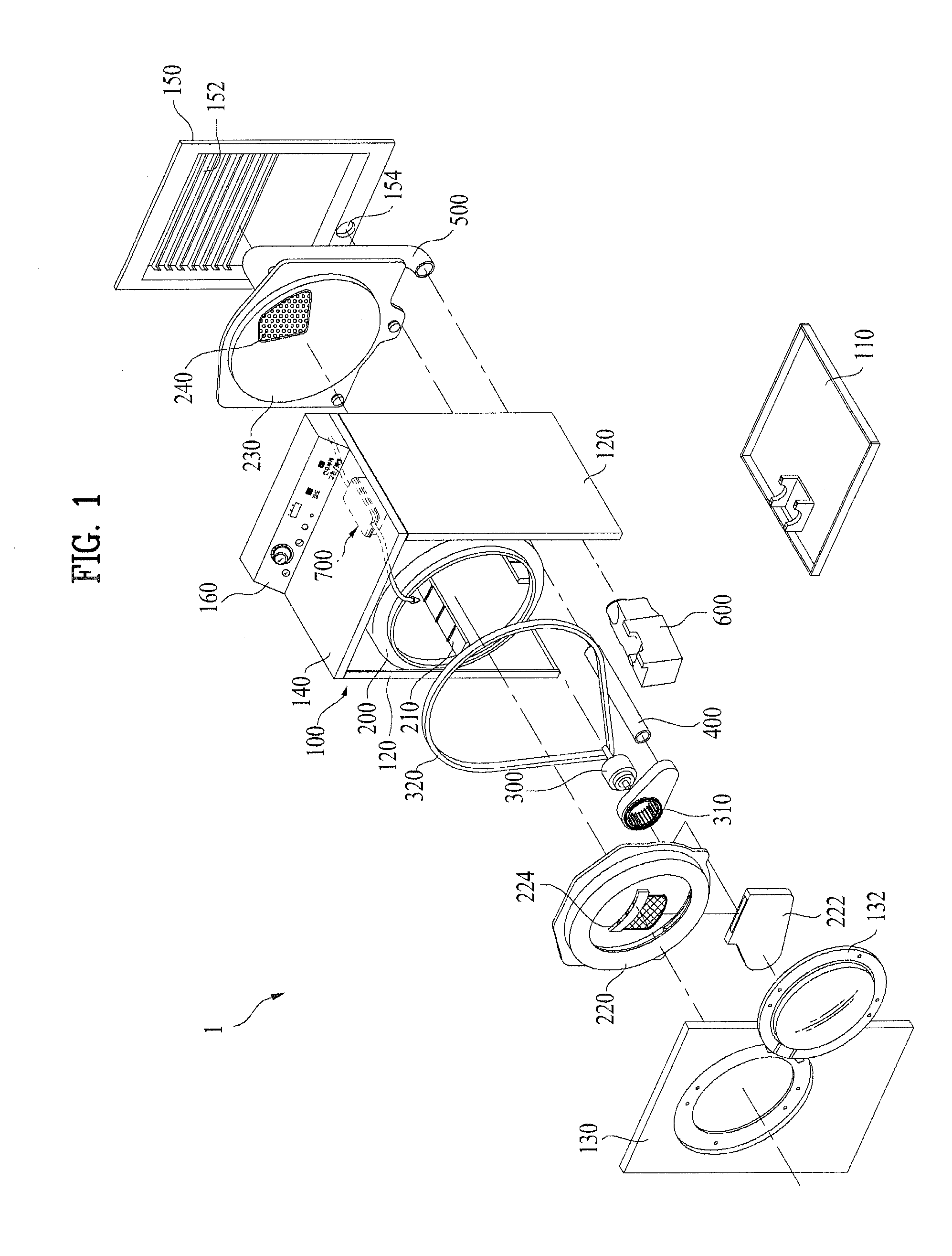
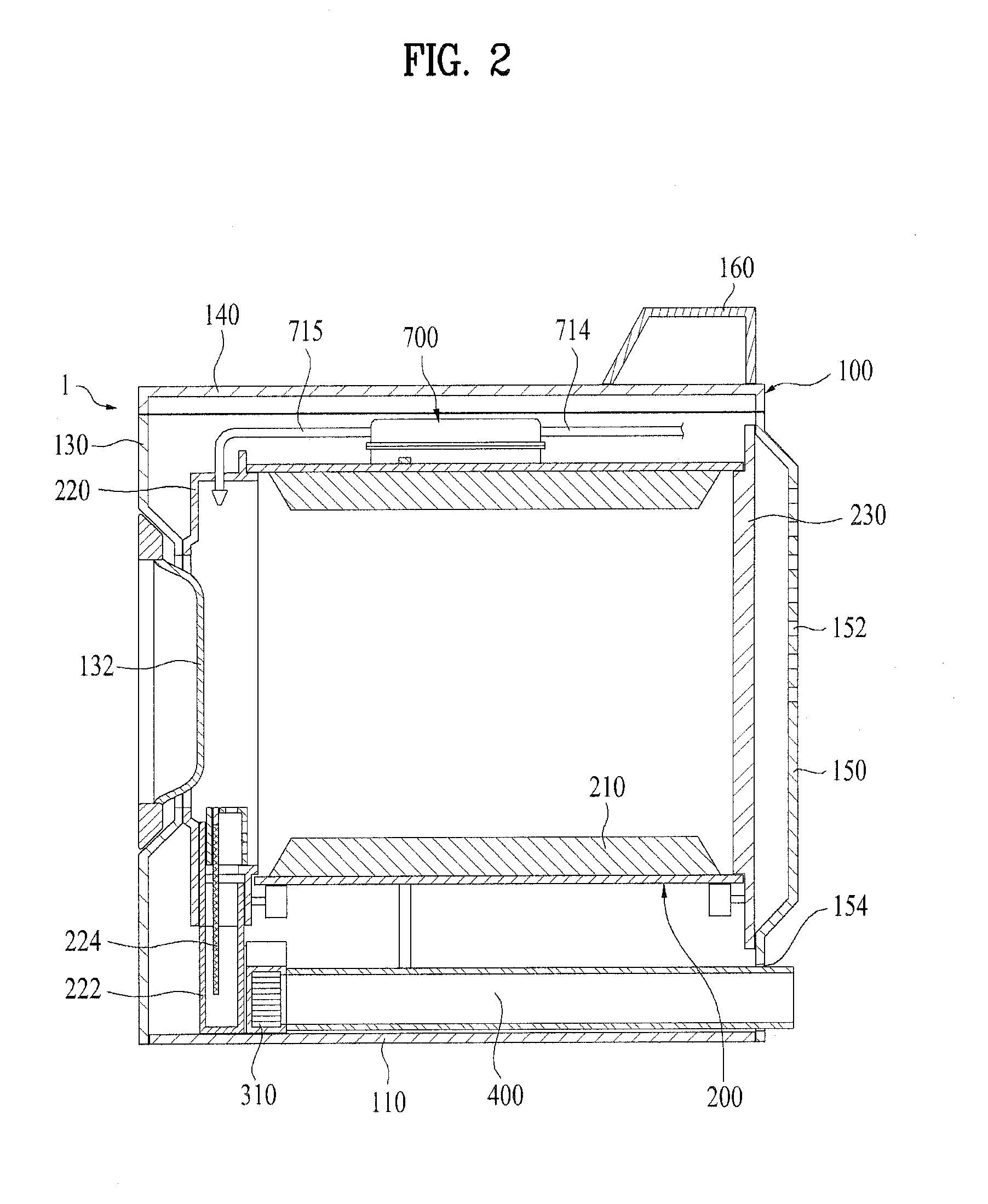
[0011]An object of the present invention, devised to solve above problems, is to provide a cloth treating apparatus in which structures of a heat pump and a steam generator which generate heat in the cloth treating apparatus to generate hot air and steam are improved for reducing power required for steam generation and increasing steam generating efficiency.
[0012]Another object of the present invention, devised to solve above problems, is to provide a cloth treating apparatus in which a plurality of evaporators and condensers are provided for enhancing condensing efficiency and heating efficiency, and accurate refrigerant temperature sensing is made for controlling a driving speed of a compressor to suppress noise and vibration generation to minimum.
[0013]Another object of the present invention, devised to solve above problems, is to provide a cloth treating apparatus which can remove lint carried by the air and accumulated on heat exchangers from the heat exchangers, such as a condenser or an evaporator.
[0027]Preferably, the lint removing means further includes a fan for blowing air to the drum, and the fan is provided as a reversible fan which can blow the air in regular / opposite directions for blowing the air in a direction opposite to a direction of the air blow at the time of drying at the time of lint removal.

Problems solved by technology

However, since the heat pump has a temperature elevating range lower than the electric type heater or the gas type heater, the heat pump has relatively low air heating efficiency, to require a longer drying time period.
Moreover, accumulation of lint carried by the air both on the evaporator which removes moisture from the air and the condenser which heats the air of the heat pump makes heat efficiency poor.
The cloth treating apparatuses having steam generators consume energy additionally compared to the cloth treating apparatus without the steam generator.

Method used


Image

  • Cloth treating apparatus
  • Cloth treating apparatus
  • Cloth treating apparatus

Examples


Embodiment Construction

[0040]Terms of elements defined in describing the present invention have been made taking functions thereof in the present invention into account. Therefore, it is required to understand that the terms do not limit technical elements of the present invention. Moreover, the terms of the elements may be called in other terms in this field of art.

[0041]In order to describe the cloth treating apparatus of the present invention, a drum type cloth treating apparatus will be taken as an example for convenience's sake. However, the present invention is not limited to this, but the cloth treating apparatus of the present invention is applicable to a cabinet type cloth treating apparatus having immovable drying space, and a washing machine having a drying function.

[0042]And, the drying objects mentioned in this specification includes, not only clothes, apparel, but also objects people uses, such as a doll, a handkerchief, blanket, along with objects a person can wear, such as shoes, socks, gl...


PUM


Abstract

The present invention relates to a cloth treating apparatus, including a cabinet which forms an exterior thereof, a drum rotatably mounted to the cabinet, a heat pump for supplying hot air to the drum, a steam generator for supplying steam to the drum, and a water tank for supplying water to the steam generator, wherein the water tank is positioned on a refrigerant flow passage of the heat pump, thereby increasing steam generating efficiency by elevating an initial temperature of the water used for the steam generation.

Description

CROSS REFERENCE TO RELATED APPLICATION[0001]Pursuant to 35 U.S.C. §119(a), this application claims the benefit of earlier filing date and right of priority to Korean Patent Application Nos. 10-2010-0042777, filed on May 7, 2010, 10-2010-0039373 filed on Apr. 28, 2010, 10-2010-0041999 filed on May 4, 2010 and 10-2010-0039368 filed on Apr. 28, 2010, which are hereby incorporated by references as if fully set forth herein.BACKGROUND OF THE DISCLOSURE[0002]1. Field of the Disclosure[0003]The present invention relates to cloth treating apparatuses, and more particularly, to a cloth treating apparatus in which a heat pump supplies hot air to a drum, and has an improved supply structure of water to be used for supplying steam.[0004]2. Discussion of the Related Art[0005]Recently, along with washing machines which wash clothes, different kinds of cloth treating apparatuses are used, such as drum type dryers for drying wet washed clothes, and cabinet type cloth treating apparatuses in which t...

Claims


Application Information

Patent Timeline
IPC IPC(8): F26B21/00
CPCD06F39/008D06F58/203D06F2058/287D06F58/28D06F58/206D06F2103/50D06F2105/26D06F58/30D06F2103/58D06F58/20D06F34/20D06F39/40
Inventor LEE, YONGJULEE, SANGIKNOH, HYUNWOO
Owner LG ELECTRONICS INC
Learn More