
Vascular stent design

a stent and vascular technology, applied in the field of radially expandable vascular stent design, can solve the problems of recurrent problems, increased risk of late stent thrombosis, death or myocardial infarction, etc., and achieve the effect of reducing or eliminating local flow disturbances, and facilitating inhibition of thrombosis and inflammation

Inactive Publication Date: 2011-11-10
THE TRUSTEES OF THE UNIV OF PENNSYLVANIA
View PDF4 Cites 22 Cited by
  • Summary
  • Abstract
  • Description
  • Claims
  • Application Information

AI Technical Summary

Benefits of technology

[0018]Accordingly, it is one object of the present invention to minimize or eliminate local flow disturbances that lead to a pro-thrombotic and pro-inflammatory environment at and around the struts of a radially expandable surgical stent.
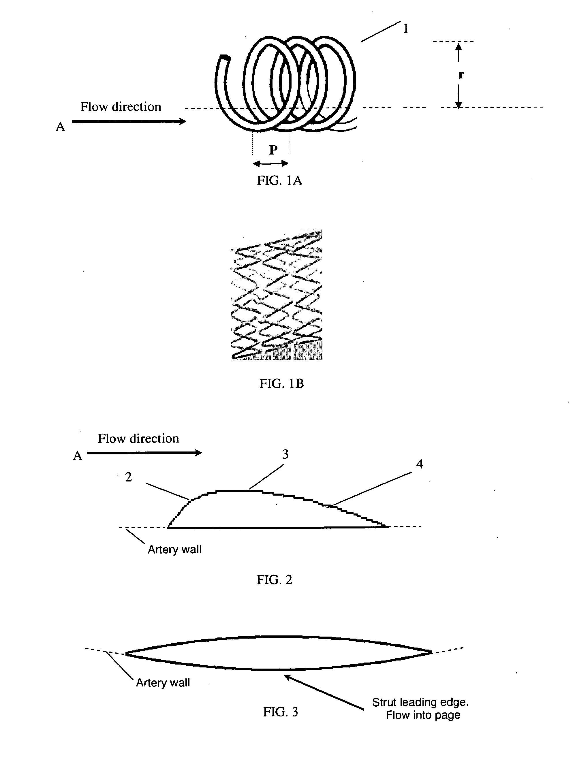
[0020]In accordance with these and other objects of the invention, one embodiment of the invention provides a stent whose struts have an inner surface contour design and cross-sectional geometry that streamline the strut-blood and strut-vessel interfaces to create a fluid dynamic and pressure distribution environment that is more conducive to inhibition of thrombosis and inflammation.

Problems solved by technology

However, restenosis, the re-formation of a neointima that re-narrows the arterial lumen, is a recurrent problem in ˜30% of patients receiving bare metal stents (BMS).
Unfortunately, recent studies suggest a small but significantly increased risk of late stent thrombosis in DES patients that results, in the majority of cases, in death or myocardial infarction.
Advanced plaques often develop a pro-thrombotic surface in contact with the blood, resulting in thrombotic emboli or resident clots.
Similar regions occur naturally in the arterial circulation at branches, bifurcations and sharp curvatures where separated flow within the region occurs as a result of the geometric changes in the vessel, and such regions are susceptible to atherosclerosis and its associated thrombotic and inflammatory risks.
Of particular note is that exposure of blood to the stent may continue for months after deployment of DES, extending the thrombotic and inflammatory risks.
Thus, the present stent configurations do not accommodate a design that minimizes flow disturbances as the blood passes over the stent struts.
By largely ignoring the hemodynamic interactions between the flowing blood and the stent surface profiles, a higher risk of stent-induced thrombosis persists while the stent is at or near the artery surface.
Therefore, thrombosis risk for BMS is greatest during the first weeks to months after deployment.
However, while the inner surface of the struts may indeed have a smoothed contour, it is clear that the curvature disclosed exceeds that required to mitigate or eliminate flow separation at physiological Reynolds numbers and that the geometry of the strut surface relative to the lumen wall will still result in significant flow separation of the blood as it passes over the strut.
However, while the geometry of the disclosed stent struts have an outer surface that may indeed reduce the injury and inflammation to the vessel wall, there is no indication that the geometry of the inner surface of the struts reduces flow separation of the blood as it passes over the struts as intended.
In carotid arteries that supply blood to the brain, severe atherosclerosis may narrow the vessels reducing blood flow or causing blood clots to form at the plaque sites.
Often, thrombotic emboli detach resulting in a stroke or a series of transient episodes of ischemia in the brain.

Method used


Image

  • Vascular stent design
  • Vascular stent design
  • Vascular stent design

Examples


example 1

Blood Flow across the Struts is Different between Streamlined and Nonstreamlined Stents

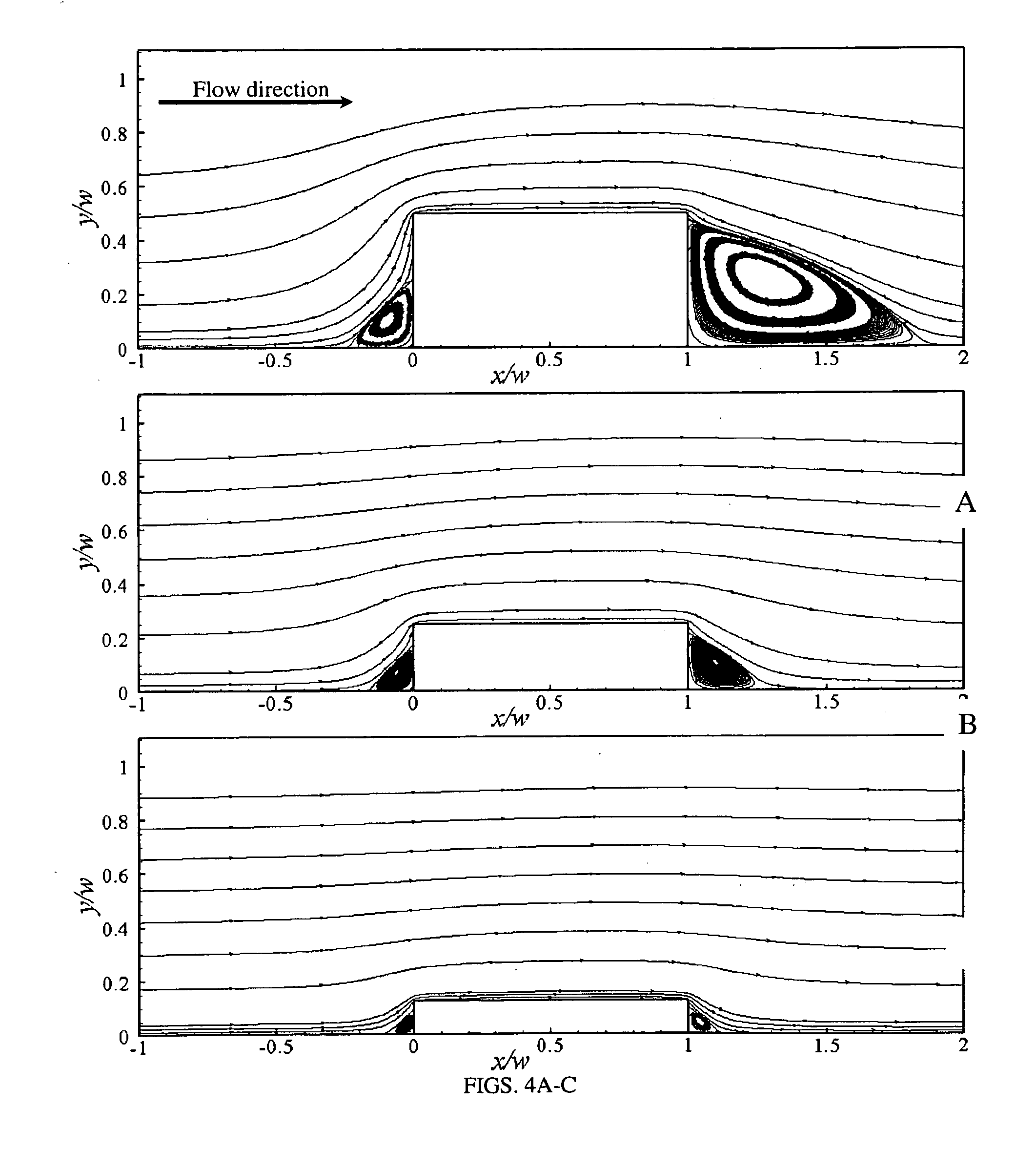
[0090]The fluid flow domain shown in FIG. 1 was studied using CFD to better understand the effects of six streamlined and nonstreamlined stent strut geometries with varying aspect ratios, AR, in a blood vessel (FIG. 12). The coordinates on the plots shown in this section have been modified for ease of presentation without any modifications to the data. Axes corresponding to distance have been nondimensionalized by w and the location of the leading edge of the third strut has been redefined as x / w=0. In this study there is no focus on the strut-to-strut flow field variations, but on a representative case. Qualitatively the flow field about a strut is similar to that of its neighboring struts, but quantitative differences can be observed since the effects due to the presence of neighboring struts compounds as the flow travels downstream in the blood vessel. The effect is greater for thicker struts.

example 2

Pressure Field

[0091]FIGS. 4 and 5 shows the nondimensionalized pressure field in the vicinity of the struts with streamlines in the foreground. The pressure was nondimensionalized by dividing the static pressure by the dynamic pressure,

p*=p12ρU_2.

A higher pressure region is present for each case on the upstream side of the strut. The pressure gradient weakens as the height, h, decreases. The flow fields along the top surfaces of the struts experience a pressure decrease as x / w increases, but upstream of the struts the pressure increases as it approaches x / w=0. The upstream influence of the strut increases as the height of the strut increases. Since the flow studied is laminar and steady, the superimposed streamlines in FIGS. 4 and 5 correspond to the path a fluid element traveled in space. A significant recirculation region, as denoted by the streamlines, is present both upstream and downstream of the 2:1 rectangular geometry (FIG. 4a). Similar results are observed on the upstream a...

example 3

Separation Zone Cross-Sectional Area

[0092]Table 2 shows the upstream and downstream separation areas normalized by the separation area of the rectangular 8:1 aspect ratio strut. The upstream separation zones corresponding to the rectangular 4:1 and 2:1 cases, increased 3.8 and 8.4 times, respectively, when compared to that of the 8:1 aspect ratio strut. Correspondingly, the up stream separation zone for the 2:1 circular arc increased 20%. The downstream separation area increased nonlinearly from 5.7 to 42.2 times for the 4:1 and 2:1 rectangular struts, respectively. The downstream separation zone for the 2:1 circular arc increased about 14.4 times with respect to the downstream separation zone of the rectangular 8:1 aspect ratio strut, which is a significantly larger increase than the increase observed for the upstream side, but significantly lower than that observed for the 2:1 rectangular strut. The upstream separation zone for the rectangular 4:1 case is larger than that for the ...


PUM


Abstract

This invention is directed to the design of radially expandable vascular stents to optimize hemodynamic flow characteristics that are favorable for the inhibition of stent-associated thrombosis, inflammation, and restenosis (neointimal formation) and that will reduce the risk of adverse events post-deployment.

Description

FIELD OF THE INVENTION[0001]This invention relates to the design of radially expandable vascular stents to optimize hemodynamic flow characteristics that are favorable for the inhibition of stent-associated thrombosis, inflammation, and restenosis (neointimal formation) and that will reduce the risk of adverse events post-deployment.BACKGROUND OF THE INVENTION[0002]In coronary arteries, at sites where atherosclerosis is present, there often occurs a stenosis that reduces blood flow to the myocardium and leads to angina or to an infarction. Deployment of one or more radially expandable vascular stents is a common procedure of choice in order to physically reopen stenotic regions of coronary arteries, i.e., to locally restore the diameter of the lumen, and enhance the flow of blood to the myocardium. However, restenosis, the re-formation of a neointima that re-narrows the arterial lumen, is a recurrent problem in ˜30% of patients receiving bare metal stents (BMS).[0003]To counter rest...

Claims


Application Information

Patent Timeline
Patent Type & Authority Applications(United States)
IPC IPC(8): A61F2/82A61F2/06
CPCA61F2/88A61F2250/0013A61F2002/068A61F2/91
Inventor DAVIES, PETER F.JIMENEZ, JUAN M.
Owner THE TRUSTEES OF THE UNIV OF PENNSYLVANIA
Learn More