
System and method for allocating transmission resources

a transmission resource and resource allocation technology, applied in the field of wireless communication, can solve the problems of increasing the complexity of managing radio channels, failing to provide optimal allocation of transmission resources between control information, etc., and achieve the effect of simplifying the processing of multi-antenna transmissions and increasing the benefits of transmission diversity

Active Publication Date: 2011-11-10
TELEFON AB LM ERICSSON (PUBL)
View PDF6 Cites 33 Cited by
  • Summary
  • Abstract
  • Description
  • Claims
  • Application Information

AI Technical Summary

Benefits of technology

[0009]Important technical advantages of certain embodiments of the present invention include increasing the benefits gained from transmission diversity and simplifying processing of multi-antenna transmissions. Particular embodiments enable control information and user data to be divided into separate vector symbols so that control and data are time multiplexed, as opposed to being transmitted in parallel. In particular embodiments, this separation may be attained without incurring significant additional control overhead and may enable reuse of conventional uplink processing modules. Other advantages of the present invention will be readily apparent to one skilled in the art from the following figures, descriptions, and claims. Moreover, while specific advantages have been enumerated above, various embodiments may include all, some, or none of the enumerated advantages.

Problems solved by technology

While MIMO transmission techniques can significantly increase throughput, such techniques can greatly increase the complexity of managing radio channels.
As a result, such resource allocation solutions fail to provide optimal allocation of transmission resources between control information and user data when MIMO techniques are being utilized to transmit data on multiple layers simultaneously.

Method used


Image

  • System and method for allocating transmission resources
  • System and method for allocating transmission resources
  • System and method for allocating transmission resources

Examples


Embodiment Construction

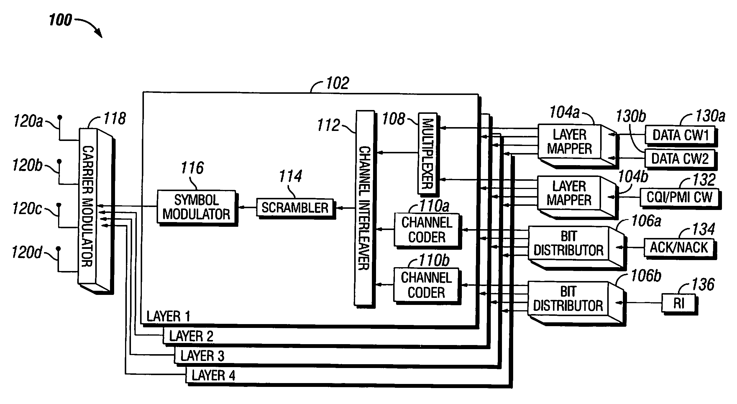
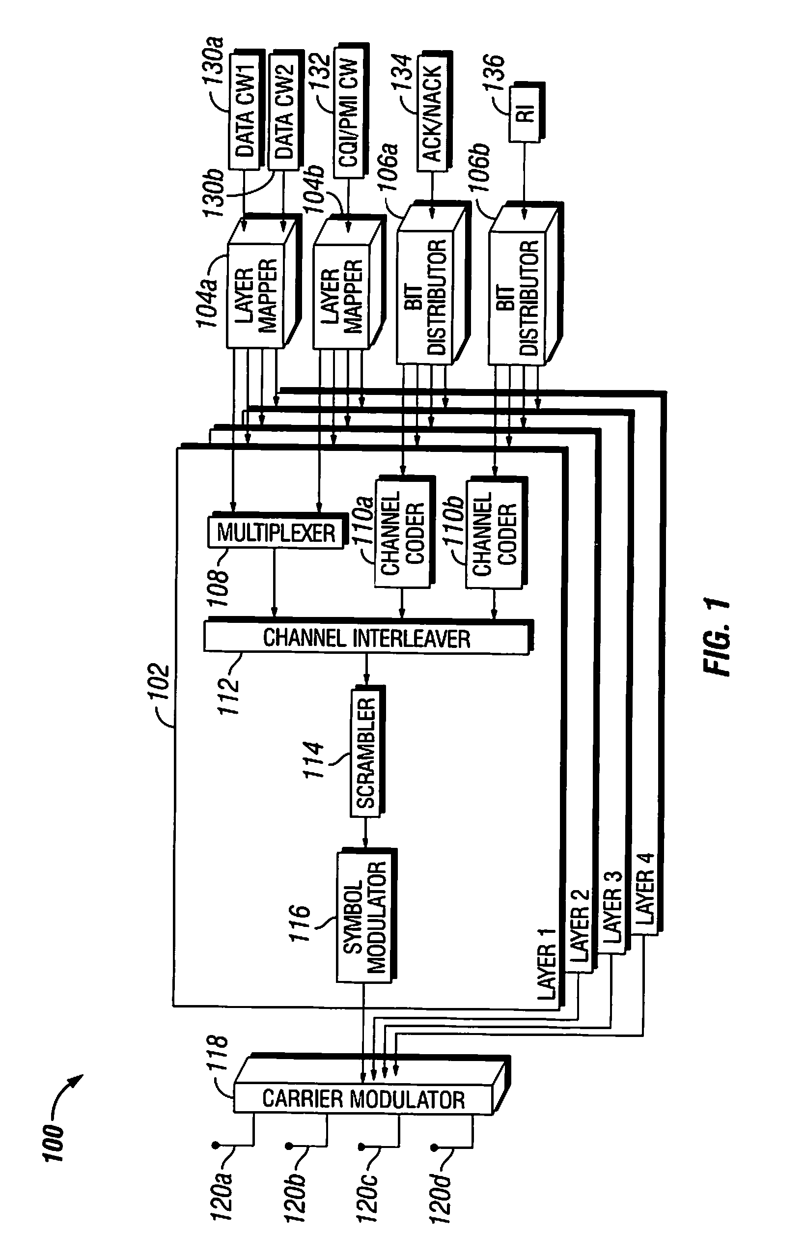
[0021]FIG. 1 is a functional block diagram illustrating a particular embodiment of a multi-antenna transmitter 100. In particular, FIG. 1 shows a transmitter 100 configured to multiplex certain control signaling with user data for transmission over a single radio channel. By intelligently implementing the coding, interleaving, layer mapping, and other aspects of the transmission, transmitter 100 may be able to improve upon the resulting allocation of user data and control signaling to transmission resources, as described further below.

[0022]Control signaling can have a critical impact on the performance of wireless communication systems. As used herein, “control signaling” and “control information” refers to any information communicated between components for purposes of establishing communication, any parameters to be used by one or both of the components in communicating with one another (e.g., parameters relating to modulation, encoding schemes, antenna configurations), any infor...


PUM


Abstract

A method for wirelessly transmitting user data and at least a first type of control information using a plurality of transmission layers including encoding bits of a first type of control information to form one or more control codewords and encoding bits of user data to form one or more user data codewords. The method also includes generating a plurality of vector symbols based on the control codewords and the user data codewords. Each vector symbol includes a plurality of modulation symbols that are each associated with a transmission layer over which the associated modulation symbol will be transmitted. Generating the plurality of vector symbols includes interleaving bits of the one or more control codewords and bits of the one or more user data codewords so that the first type of control information is carried in modulation symbols associated with the same transmission layers in all the vector symbols transmitted during the subframe that carry the first type of control information. The method also includes transmitting the plurality of vector symbols to a receiver over a plurality of transmission layers.

Description

PRIORITY CLAIM UNDER 35 U.S.C. §119(e)[0001]This application claims the benefit of U.S. Provisional Application No. 61 / 332,867, filed May 10, 2010, entitled “Uplink Codeword-to-Layer Mapping for Improved Separation of UCI and Data,” which is incorporated by reference in its entirety.TECHNICAL FIELD OF THE INVENTION[0002]This disclosure relates in general to wireless communication and, more particularly, to resource allocation for multi-antenna transmissions.BACKGROUND OF THE INVENTION[0003]Multi-antenna transmission techniques can significantly increase the data rates and reliability of wireless communication systems, especially in systems where the transmitter and the receiver are both equipped with multiple antennas to permit the use of multiple-input multiple-output (MIMO) transmission techniques. Advanced communication standards such as Long Term Evolution (LTE) Advanced utilize MIMO transmission techniques that may permit data to be transmitted over multiple different spatially...

Claims


Application Information

Patent Timeline
Patent Type & Authority Applications(United States)
IPC IPC(8): H04L27/00H04B1/38H04J13/00
CPCH04L1/003H04L1/0071H04L1/0079H04L1/1664H04W72/0413H04L5/0053H04B7/0413H04L5/0091H04L1/1671H04B7/0486H04L5/00H04B7/04H04W72/04H04B7/0669H04L25/03929H04W72/20H04W72/21H04B7/0456H04L5/0057
Inventor HAMMARWALL, DAVIDJONGREN, GEORGE
Owner TELEFON AB LM ERICSSON (PUBL)
Learn More